RED ONE Quick Start Manual
Hide thumbs
Also See for ONE:
- Operation manual (80 pages) ,
- Operation manual (132 pages) ,
- Operation manual (120 pages)
Table of Contents
Advertisement
Quick Links
Advertisement
Table of Contents

Related Manuals for RED ONE


Summary of Contents for RED ONE
- Page 2 THANKS Congratulations and thank you for your purchase of a RED ONE™ camera. Before un- packing and assembling the camera body and any accessories, please review the QUICK START GUIDE. If there is any physical damage to your camera or accessories, please contact us immediately at info@red.com.
-
Page 3: Bottom Plate
Ensure shoulder dovetail lock is on “R” side of RED ™ logo and slide into bottom plate. Install end with RED ™ logo facing rear of camera. Secure in place by sliding lock to “D” side of RED ™ logo. -
Page 4: Top Mount
INSTALLED Extend attachment arm on cradle assembly and install base to universal mount using one (1) button-head Allen bolt (and two (2) Allen bolts, if desired). 10. Adjust and secure cradle assembly. CRADLE MOUNT INSTALLED ON UNIVERSAL MOUNT... - Page 5 13. Install top handle (pointing toward rear of camera) using two (2) Allen bolts. TOP HANDLE INSTALLED 14. Assemble right handle, wing nuts and washers - do not tighten. 15. Slide right handle over front of either rod. Lock in place using wing nut. FRONT CAMERA NOTE:...
- Page 6 • RED DRIVE®: Loosen thumb screws on sides of cradle assembly, slide into v-blocks in cradle and tighten thumb screws. Connect 90˚ end of cable to RED DRIVE® and straight end to DRIVE connector on rear of camera. SD MEMORY...
- Page 7 TO CAMERA 22. Slide RED BRICK® battery into v-mount battery plate on Cradle Assembly. NOTE: To ensure a good connection between battery and RED Cradle V-plate adapter, it is recommended to perform a break-in sequence. To break-in: Fully engage/disengage a RED BRICK®...
-
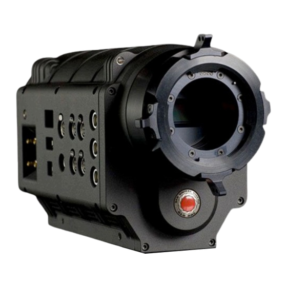
Page 8: Camera Controls
This section describes the physical controls and connectors on the RED ONE™ camera. LEFT FRONT OF CAMERA On the left front of the camera body are a RECORD button (RED) to start and stop recording and two (2) User Buttons. User Button 1 is pre-assigned to AUTO WB (White balance) and User Button 2 is pre-assigned to 1:1 FOCUS CHECK, these button can be reprogrammed as desired. -
Page 9: Power On/Off
Five buttons above the LCD display control clip playback. From left to right,Clip Start / Previous Clip, Reverse, Clip Play / Pause, Fast Fwd and Clip End / Next Clip. DISPLAY SHOWING: PIN, BUILD AND VERSION POWER ON/OFF SWITCH Underneath the status display buttons are (from left to right) the Power On/Off switch, 2 - 4-Pin Auxiliary Power / GPIO outputs (AUX 12V), 6-Pin camera system DC POWER input and a 16-Pin DRIVE External Memory interface. - Page 10 • When using a RED BRICK® battery, press the power on/off switch once. • When using a RED-CHARGER, connect it via the supplied power cable. Plug the RED-CHARGER into an AC power source and switch it on. After the green LED illuminates on the RED-CHARGER, the camera can be powered on by pressing the On/Off switch.
-
Page 11: Back Focus Adjustment
8. The “Edge Highlight” option in the view nder menu is a handy tool (if view nder is installed), and can serve as a good double-check for proper focus. Refer to the RED ONE™ OPERATION GUIDE available at www.red.com/support... -
Page 12: Fcc Rules
• For additional information refer to the latest version of the RED ONE™ OP- ERATION GUIDE available at www.red.com/support. FCC RULES •...
Need help?
Do you have a question about the ONE and is the answer not in the manual?
Questions and answers