RED ONE Operation Manual
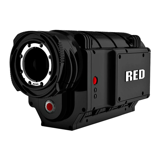
Red one camera
Hide thumbs
Also See for RED ONE:
- Operation manual (80 pages) ,
- Operation manual (132 pages) ,
- Quick start manual (13 pages)
Table of Contents
Advertisement
Quick Links
Download this manual
See also:
Operating Manual
Advertisement
Table of Contents

Related Manuals for RED RED ONE


Summary of Contents for RED RED ONE
- Page 2 THIS PAGE INTENTIONALLY BLANK...
-
Page 3: Table Of Contents
Recording ............27 Slate ............... 56 Playback ............. 28 Configure ............57 SENSOR MENU CONTROLS ......... 29 Timecode ............60 Sensitivity ............29 QT Proxies ............. 62 Color Temp ............30 Monitor ............... 62 VERSION 20.1.3 AUGUST 5, 2009 ©2009 RED.COM INC. - Page 4 RED™ QuickTime Codec ......113 APPENDIX C: SAVING LOOK/USER RED Alert! ® ..........113 PROFILE ..............97 REDCINE® ........... 116 Look ..............97 RED ONE Operation Guide Camera Build Version 20.1.3 August 5, 2009 VERSION 20.1.3 ©2009 RED.COM INC. AUGUST 5, 2009...
-
Page 5: Disclaimer
All rights reserved. No part of this document may be reproduced, transmitted, transcribed, or translated into any language in any form without the prior written consent of RED™. TRADEMARKS RED ONE™, MYSTERIUM®, RED™, RED DIGITAL CINEMA™, REDCINE®, RED BRICK®, REDFLASH™, RED-RAM®, RED-DRIVE®, REDSPACE™, RED Alert! ®, R3D™, and REDCODE™ are trademarks of RED.COM, INC. -
Page 6: Before You Start
BEFORE YOU START Congratulations on your purchase of a RED ONE™ camera. Please read the attached safety instructions, then carefully unpack the camera body any accessories. If there is any physical damage or missing com- ponents for your camera body and any accessories, please file a support ticket at www.RED.com/support. - Page 7 Storage range: -20°C to +50°C (-4°F to 122°F) If there are any performance issues with your camera or accessories within this operating range, please file a support ticket on www.RED.com/support. MOISTURE: Avoid exposing your camera to moisture. The unit is not waterproof, so contact with water could cause permanent damage to the unit as well as electric shock and serious injury to the user.
-
Page 8: Camera Controls, Connectors And Displays
Figure 1 – Left Front Camera Controls A PL Lens mount is provided as standard with the RED ONE™ camera. The mount is compatible with the majority of S35mm, 35mm and S16mm cinematography lenses. In addition, broadcast B4 mount lenses may be used if the camera is equipped with the optional B4 to PL mount optical converter. -
Page 9: Rear Of Camera
NOTE: If PLAYBACK LOOK preference is set to CLIP, the color adjust metadata will be read from the recorded clip. If set to CAMERA, the metadata used are the current camera settings. VERSION 20.1.3 AUGUST 5, 2009 ©2009 RED.COM INC. - Page 10 The status display reports key camera status values, and is complimented by two LED’s (I): the REC LED provides record status (illuminates Red when recording), while the OK LED indicates the camera is ready for operation (illuminates Green when ready). VERSION 20.1.3 ©2009 RED.COM INC. AUGUST 5, 2009...
-
Page 11: Undo/Exit Buttons
Down to go to next menu (similar to Push to select a menu item). Rotate (turn/twist like a knob) changes value in highlighted box. Push (like a button) to enter a selection. VERSION 20.1.3 AUGUST 5, 2009 ©2009 RED.COM INC. -
Page 12: Power On/Off Switch
Power on/off switch (A) is located on the lower rear of the camera. Press once to power up/power down the camera. Power ON / Off Switch Figure 4 – Rear Lower Camera Controls VERSION 20.1.3 ©2009 RED.COM INC. AUGUST 5, 2009... -
Page 13: Camera Connectors
CAMERA CONNECTORS RIGHT SIDE OF CAMERA This section describes the physical connectors on the RED ONE™ camera body. For detailed description and operation refer to APPENDIX D: INPUT/OUTPUT CONNECTORS. Headphone USB Slave Program HD-SDI (A) Audio Out Program HD-SDI (B) Timecode Audio In Ch 1 –... -
Page 14: Rear Of Camera
LAPSE in GPIO preferences) and a Frame Recorded Tally output. DRIVE interface supplies power and data over e-SATA protocols to record REDCODE™ (TM) RAW compressed video data, metadata and audio to RED-DRIVE® or RED-RAM® digital media. VERSION 20.1.3 ©2009 RED.COM INC. AUGUST 5, 2009... -
Page 15: Camera Displays
CAMERA DISPLAYS The LCD status display mounted at the rear of the RED ONE™ camera provides a snapshot of the camera setup. RED™ LCD and RED™ EVF monitors are factory preset digital displays. There are no saturation, peaking or contrast adjustments as found on analog monitors to correct color reproduction. -
Page 16: Red Lcd Display
The RED™ EVF comprises the following components: A. High-resolution color display: Provides a 1280 pixel x 848-pixel resolution progressive scan color im- age equivalent to viewing a 17” reference color monitor from a distance of approximately 4 ft. VERSION 20.1.3 ©2009 RED.COM INC. AUGUST 5, 2009... -
Page 17: External Hd-Sdi Or Hdmi Monitors
Refer to CAMERA CONNECTORS. To aid external monitor alignment, the RED ONE™ camera provides a range of test signals including SMPTE Bars, Back and White Fields, Luma and Chroma Ramps, and a Chip Chart. Refer to TEST SIG- under MONITOR in SYSTEM MENU CONTROLS. -
Page 18: Theory Of Operation
A B4 mount to PL mount adaptor is also available to permit use of 2/3” HD lenses on the RED ONE™ camera. The optical coverage it provides is equivalent to S16 mm. Hence, the maximum recording resolu- tion with these lenses will be 2K RAW. -
Page 19: Line Level Inputs
Signal to Noise Ratio for the resulting 24-bit digital recording. VIDEO MONITORING OUTPUTS In its default configuration, the RED ONE™ camera can simultaneously support a RED™ EVF, RED™ LCD, 3 HD-SDI outputs and one HDMI output, with two of these outputs supporting full GUI overlay graphics. -
Page 20: Red Lcd And Red Evf
System information including instantaneous frame rate, sensitivity, shutter speed, color temperature, re- cording format, clip name, timecode, battery and media remaining is provided in the RED™ LCD or RED™ EVF monitor outputs, and the rear status display on the camera back. VERSION 20.1.3 ©2009 RED.COM INC. AUGUST 5, 2009... - Page 21 For applications where a RED™ LCD or RED™ EVF are not desired – for example working on a crane – the Surround View video, frame guides, and exposure overlays are also available on the Preview HD-SDI output, providing remote camera monitoring up to 200 ft away. VERSION 20.1.3 AUGUST 5, 2009 ©2009 RED.COM INC.
-
Page 22: Record Indicator
RECORD INDICATOR When recording, the RED ONE™ camera provides a variety of record indications (tallies): Timecode, normally displayed in white colored text, will turn red A small red dot will appear in the top left corner of any video monitoring outputs (RED™ LCD, etc…) -
Page 23: Digital Magazines
MEDIA. METADATA RED ONE™ cameras record Metadata, which is data that describes the precise characteristics of the pic- ture and sound data, in each frame of footage. This may include camera specific setup information, project and clip management information, Edge code, Time code, date and GMT, lens parameters, audio settings and any video image processing information. -
Page 24: Smpte Timecode
001or other desired value. SMPTE TIMECODE As each recording is made, the RED ONE™ camera records two independent timecode tracks. Edge Code is a SMPTE timecode track that always starts at 1.00.00.00 on the first frame of each piece of digital media. -
Page 25: Basic Operation
BASIC OPERATION This section describes powering up/down and basic controls of the RED ONE™ camera and how to in- itiate a project. POWER UP / DOWN Power is supplied to the camera via a RED-BRICK® battery (connected through a RED™ BATTERY PLATE, RED™... -
Page 26: Operating Camera Using Red Charger
3. Insert a battery into one of the two V-plate adapters. Insert second battery if desired. 4. Observe the charger LED. In addition, the charge status will read in 20% steps through the RED- BRICK® battery LED array. RED-BRICK® battery LED array VERSION 20.1.3 ©2009 RED.COM INC. AUGUST 5, 2009... -
Page 27: Connecting Media
FIRST TIME USE - SETTING UP A PROJECT Before recording, the camera must be instructed to follow a Record Quality, Frame Rate and Resolution. These values are set in the PROJECT sub menu located in the SYSTEM menu. VERSION 20.1.3 AUGUST 5, 2009 ©2009 RED.COM INC. -
Page 28: Resolution
On playback these recordings will be displayed at the Project Frame Rate NOTE: If operating on a multi-camera production, enter a different Camera I.D for each camera us- ing the SLATE menu; otherwise skip this step; the camera is ready to shoot. VERSION 20.1.3 ©2009 RED.COM INC. AUGUST 5, 2009... -
Page 29: Time Base (Formerly Frame Rate)
RAW footage. Time Code and Edge Code values used by the camera are Non Drop Frame (NDF); Drop Frame (DF) is not supported. Audio is captured at 48KHz 24-bit resolution per channel, uncompressed. VERSION 20.1.3 AUGUST 5, 2009 ©2009 RED.COM INC. -
Page 30: Playback
Windows is not currently supported. PLAYBACK Playback of recorded clips is available on-camera using the buttons located above the LCD display. Refer CAMERA CONTROLS under CAMERA CONTROLS, CONNECTORS AND DISPLAY for complete in- formation. VERSION 20.1.3 ©2009 RED.COM INC. AUGUST 5, 2009... -
Page 31: Sensor Menu Controls
1. To adjust, twist joystick (like a knob) to change the highlighted SENSITIVITY box to the desired setting (default is ISO 320). 2. Push up on the joystick to set and return to the previous menu (SENSOR main menu) or push the EXIT button to exit the menu completely. VERSION 20.1.3 AUGUST 5, 2009 ©2009 RED.COM INC. -
Page 32: Color Temp
Shutter speed presets are available for all common speeds (and corresponding angles) at 24 / 25 fps and 50 / 60 fps. Preset shutter speeds may be adjusted using the RELATIVE and SYNCRO shutter parameters. VERSION 20.1.3 ©2009 RED.COM INC. AUGUST 5, 2009... -
Page 33: Genlock
Exposure times presets include: 1/24, 1/25, 1/30, 1/32, 1/33, 1/40, 1/48, 1/50, 1/60, 1/96, 1/100, 1/120, 1/125, 1/192, 1/200, 1/250, 1/384, 1/400, 1/500, 1/696, 1/800, 1/1,000, 1/1,200, 1/2,000 sec. VERSION 20.1.3 AUGUST 5, 2009 ©2009 RED.COM INC. -
Page 34: Syncro
- 45 to + 45 degrees. Default value is 0. To adjust: Select PHASE and twist joystick (like a knob) to change the highlighted PHASE ADJUST box to the desired setting. VERSION 20.1.3 ©2009 RED.COM INC. AUGUST 5, 2009... -
Page 35: Varispeed
This ensures that the recorded REDCODE™ RAW data has valid and sequentially in- crementing timecode for use by non-linear editing devices. Note: In Varispeed, the frame rate display turns yellow, the audio panel reports VARISPEED. VERSION 20.1.3 AUGUST 5, 2009 ©2009 RED.COM INC. -
Page 36: Varispeed
On-Event: On recording start, the capture frame rate starts out at the Frame Rate, the start of the transi- tion to the End Rate occurs only when an external GPI trigger has been received. VERSION 20.1.3 ©2009 RED.COM INC. AUGUST 5, 2009... -
Page 37: Frame Rate
30 fps 30 fps 4K ANA 25 fps 30 fps 30 fps 30 fps 4K HD ---- 25 fps 30 fps 30 fps 4K 16:9 ---- 25 fps 30 fps 30 fps VERSION 20.1.3 AUGUST 5, 2009 ©2009 RED.COM INC. -
Page 38: Time
TRIGGER MODE: Specifies if the camera is to use a fixed Interval of time or wait for a side record com- mand or external GPI contact closure to initiate the next frame capture. VERSION 20.1.3 ©2009 RED.COM INC. AUGUST 5, 2009... -
Page 39: Speed
UNIQUE: Specifies that each frame captured during the burst record is unique. That is for each Time- lapse event, N frames are captured and recorded, where N is the Step print value. VERSION 20.1.3 AUGUST 5, 2009 ©2009 RED.COM INC. - Page 40 Each successive event uses the next available Edge Code and Time Code value and uses the existing clip name. This results in a complete Time-lapse sequence with a single clip name and correct timecode se- quence. To exit Time-lapse mode, push the RECORD button. VERSION 20.1.3 ©2009 RED.COM INC. AUGUST 5, 2009...
-
Page 41: Audio / Video Menu Controls
The LOOK menu permits Video, Gain and Tone values to be exported or imported from an SD Card. Look files may be read by another camera, but not RED Alert! ® or REDCINE®. Push joystick down or in to se- lect desired change. VERSION 20.1.3 AUGUST 5, 2009 ©2009 RED.COM INC. -
Page 42: Color
CODE™ RAW data being recorded. To adjust: Select the desired setting and twist joystick (like a knob) to change the highlighted box to the desired setting. SATURATION: Adjusts color saturation. Range is 0.0 (monochrome) to + 2.0 (super color). VERSION 20.1.3 ©2009 RED.COM INC. AUGUST 5, 2009... -
Page 43: Gain
RED GAIN: Adjusts the gain of the RED channel only. Range is 0.0 (no Red) to +4.0. BLUE GAIN: Adjusts the gain of the BLUE channel only. Range is 0.0 (no Blue) to +4.0. VERSION 20.1.3 AUGUST 5, 2009 ©2009 RED.COM INC. -
Page 44: Tone
TOE X: Adjusts the location of a control point along the X-axis on the tonal response curve. TOE Y: Adjust the location of a control point along the Y-axis on the tonal response curve. VERSION 20.1.3 ©2009 RED.COM INC. AUGUST 5, 2009... -
Page 45: Viewfinder Menu
Bluer colors represent underexposed areas, green is 18% ND, yellow and red colors represent more exposed areas. The above image reflects the following false color mapping relative to the stops of exposure. VERSION 20.1.3 AUGUST 5, 2009 ©2009 RED.COM INC. -
Page 46: Meter
LUMA HIST (histogram), RGB HIST, MONO HIST (RGB without color) and RAW HIST. To adjust: Select METER and twist joystick (like a knob) to change the ALALYSIS METER box to the desired setting. VERSION 20.1.3 ©2009 RED.COM INC. AUGUST 5, 2009... - Page 47 LUMA HISTOGRAM: Displays the luminance values of the RGB monitor path. RGB HISTOGRAM: Displays the RGB values of the RGB monitor path. MONO HISTOGRAM: Displays the area of the RGB values of the RGB monitor path. VERSION 20.1.3 AUGUST 5, 2009 ©2009 RED.COM INC.
-
Page 48: Assists
Zebras enable and adjust the upper and lower values for two independent Zebra indicators. One zebra may be used for highlight exposure, and the other for mid tone or shadows. By default, Zebras Confi- gure 1 is enabled and Configure 2 is disabled. VERSION 20.1.3 ©2009 RED.COM INC. AUGUST 5, 2009... - Page 49 0 and 84 (default is 0). To adjust HI IRE: Select HI IRE and twist joystick (like a knob) to change the UPPER IRE: box to the de- sired setting between 5 and 93 (default is 3). VERSION 20.1.3 AUGUST 5, 2009 ©2009 RED.COM INC.
-
Page 50: Dark Detail
Open Gate is not available in Varispeed or Ramp modes. Open Gate is not available for 50.00 or 59.94 Project Frame Rates. Video Genlock may not be available when operating in Open Gate. VERSION 20.1.3 ©2009 RED.COM INC. AUGUST 5, 2009... -
Page 51: Audio
0dB: Line Level audio inputs are designed to operate at unity gain (0dB), therefore use 0dB and set a 0dbu (- 20dBFS) line level output from the production mixer or other external signal source. +10dB: Select this value to normalize input levels when receiving a TAPE level line input (-10dB). VERSION 20.1.3 AUGUST 5, 2009 ©2009 RED.COM INC. -
Page 52: Microphone Level Inputs
Range is -12dB to + 6dB in 1dB steps. Default is 0dB. VOLUME RIGHT: Trims volume for Right output. E.g. Volume –6dB + Volume Right -1dB = -7dB Range is -12dB to + 6dB in 1dB steps. Default is 0dB. VERSION 20.1.3 ©2009 RED.COM INC. AUGUST 5, 2009... - Page 53 3L + 4R Feeds channel 3 to the left output, channel 4 to the right. Quad MixFeeds channels 1 plus 2 to the left output, and channels 3 plus 4 to the right. VERSION 20.1.3 AUGUST 5, 2009 ©2009 RED.COM INC.
-
Page 54: System Menu Controls
XLR connector to be trimmed to achieve a 0dBu / 0.775V RMS / - 20dBFS when receiving or an equiva- lent 0dBu / 0.775V RMS / - 20dBFS reference level input. 1. Select OUTPUT LEVEL and push in or down on Joystick. VERSION 20.1.3 ©2009 RED.COM INC. AUGUST 5, 2009... -
Page 55: 48V Enable
At the end of the selected pre-record period, the first chunk is overwritten. If the RECORD button is pushed while in pre-record, pre-record mode is terminated and a normal record is enabled. The timecode value and clip name are carried over between modes. VERSION 20.1.3 AUGUST 5, 2009 ©2009 RED.COM INC. - Page 56 To terminate pre-record, push the RECORD key a second time. NOTE: When using Pre-Record, the Edge Code written to the digital magazine can become discon- tinuous between clips, however Time Code is unaffected. VERSION 20.1.3 ©2009 RED.COM INC. AUGUST 5, 2009...
-
Page 57: Unmount
UNMOUNT Select to un-mount digital media from the RED ONE™ camera in a failsafe manner. The camera operating system will ensure that all files are closed, hard disk heads (if present) are parked, and CF card or RED- DRIVE® magazine is properly powered down. For detailed instructions, go to... -
Page 58: Reset
Combined with reel numbers and Slate clip numbers assigned by the camera, all clips recorded on the digital media may be uniquely identified, simplifying post-production and media archiving workflows. VERSION 20.1.3 ©2009 RED.COM INC. AUGUST 5, 2009... -
Page 59: Configure
IMPORTANT: Valid combinations of Quality, Resolution and Time Base are indicated by the phrase VALID SETTINGS. If this is crossed through, it indicates the media is too slow to record that combination of resolu- tion, project frame rate and quality. VERSION 20.1.3 AUGUST 5, 2009 ©2009 RED.COM INC. - Page 60 30 fps 30 fps 4K ANA 25 fps 30 fps 30 fps 30 fps 4K HD ---- 25 fps 30 fps 30 fps 4K 16:9 ---- 25 fps 25 fps 25 fps VERSION 20.1.3 ©2009 RED.COM INC. AUGUST 5, 2009...
- Page 61 MAX mode box before recording. This lowers the absolute image quality, but permits real time .R3D decoding and scaling to 1920 x 1080 progressive RGB when using commonly available CPU based post production applications. VERSION 20.1.3 AUGUST 5, 2009 ©2009 RED.COM INC.
-
Page 62: Timecode
CROSS GENERATE: Cross Gen activates 29.97 from 23.98 fps time code sync. The RED-ONE camera will generate a 23.98 Time Code signal for use with the camera’s 23.98 fps recording, and also generates VERSION 20.1.3 ©2009 RED.COM INC. AUGUST 5, 2009... - Page 63 Or set Date and Time to local time, and set the TIMEZONE value to 0. NOTE: Current GMT date and time can be found using this web site or equivalent service – http://wwp.greenwichmeantime.com/info/current-time.htm VERSION 20.1.3 AUGUST 5, 2009 ©2009 RED.COM INC.
-
Page 64: Qt Proxies
This sub-menu provides a selection of frame guides and safe action and safe title guides. User definable safe action and safe title guides may be saved as a USER PREFERENCE, thereby permitting the camera guides to be fully customized for any application. VERSION 20.1.3 ©2009 RED.COM INC. AUGUST 5, 2009... - Page 65 4. Move joystick left, right or up to select and exit. PROTECT ENABLE: allows you to set the safe area color to White, Black, Blue, Yellow or Red for maxi- mum color contrast with the scene you are shooting. VERSION 20.1.3 AUGUST 5, 2009 ©2009 RED.COM INC.
- Page 66 2. STYLE box will highlight to allow you to choose between CORNERS or RECTANGLE. 3. Twist joystick (like a knob) to change the highlighted STYLE box to the desired setting. 4. Move joystick left, right or up to select and exit. VERSION 20.1.3 ©2009 RED.COM INC. AUGUST 5, 2009...
- Page 67 X POSN: Adjusts the horizontal center position of the guide. Y POSN: Adjusts the vertical center position of the guide. SET: Push SET to save these parameters to non-volatile memory, exits menu and returns to normal oper- ation. VERSION 20.1.3 AUGUST 5, 2009 ©2009 RED.COM INC.
-
Page 68: Preview
Permits the video monitor outputs to be replaced with a video test pattern. To enable/disable a test signal check the box and select the desired test signal to display. Available test signals include the following: VERSION 20.1.3 ©2009 RED.COM INC. AUGUST 5, 2009... - Page 69 LUMA RAMP CHROMA RAMP CHIP CHART FOCUS PATTERN NOTE: The RED ONE™ test signals are not recordable, they are provided to help align external vid- eo monitors connected via the HD-SDI or HDMI outputs. VERSION 20.1.3 AUGUST 5, 2009 ©2009 RED.COM INC.
-
Page 70: Hd-Sdi
NOTE: When in SYNCED mode, EVF display may blank for up to 3 seconds: When existing OPEN GATE mode After exiting MAGNIFY mode when in 4K record resolution After changing between certain Varispeed frame rates VERSION 20.1.3 ©2009 RED.COM INC. AUGUST 5, 2009... -
Page 71: Setup
Key Map Preferences sub-menu. This menu permits selected menus or functions to Key Map be mapped to specific User Keys on the camera body. User keys are also referred at as Buttons. VERSION 20.1.3 AUGUST 5, 2009 ©2009 RED.COM INC. - Page 72 USER-5 key is enabled, and its function is defined in the associated list. NOTE: To reset keys to default settings, go to RESTORE. A reboot of the camera may be necessary to restore defaults. VERSION 20.1.3 ©2009 RED.COM INC. AUGUST 5, 2009...
- Page 73 RECORDING: Transitions the output of the GPO at the Start and End of a recording. Note: if in Time-lapse mode, GPO will maintain status until Time-lapse mode has been exited. PLAYING: Transitions the output of the GPO when a Clip is playing in Playback mode. VERSION 20.1.3 AUGUST 5, 2009 ©2009 RED.COM INC.
- Page 74 3,840 pixels scaled down to 1920 pixels. This signal is available on the HD Preview (HD-SDI), HD Program (Dual Link HD-SDI), RED™ EVF, and RED™ LCD outputs. RED™ EVF and RED™ LCD will display a 1280 x 720 pixel center cut of the larger 1920 x 1080 image. VERSION 20.1.3 ©2009 RED.COM INC. AUGUST 5, 2009...
- Page 75 2. FORMAT AS box will highlight. 3. Twist joystick (like a knob) to change the highlighted FORMAT AS box to the desired setting. 4. Move joystick right, up or push in to set. VERSION 20.1.3 AUGUST 5, 2009 ©2009 RED.COM INC.
- Page 76 Adjusts Ch 1 microphone audio level CH2: Adjusts Ch 2 microphone audio level SHU: Adjusts Shutter speed VAR: Adjusts Varispeed frame rate ISO: Adjusts Sensitivity rating of monitoring OFF: EVF control – Active / Disabled VERSION 20.1.3 ©2009 RED.COM INC. AUGUST 5, 2009...
- Page 77 5. Push the switch once more to lock the parameter and exit the parameter adjust mode. Status When checked, displays media, exposure and audio status on lower edge of all external monitors. When unchecked, lower edge of all external motors will be blank. VERSION 20.1.3 AUGUST 5, 2009 ©2009 RED.COM INC.
-
Page 78: Maintenance
DARD, QUIET and SILENT (default is AUTO). 2. Twist joystick (like a knob) to change the highlighted FAN MODE box to the desired setting. 3. Move joystick left, up or push in to select. VERSION 20.1.3 ©2009 RED.COM INC. AUGUST 5, 2009... - Page 79 To rectify, repeat the Black shading procedure with a lens cap installed. START 1. Select BLACK SHADING, camera monitoring outputs will display: VERSION 20.1.3 AUGUST 5, 2009 ©2009 RED.COM INC.
- Page 80 This will take about 2 minutes. During this time, the camera will display (camera LCD will display “Calibrating…”): 5. After analyzing sensor, the camera will display: 6. As the last step in the process the camera will display: VERSION 20.1.3 ©2009 RED.COM INC. AUGUST 5, 2009...
- Page 81 Restore will reset any user defined black shading data to factory default values. 1. Select BLACK SHADING, camera monitoring outputs will display: 2. Select RESTORE, camera monitoring outputs will display: 3. Select OK, camera monitoring outputs will display: 4. Restart the camera as instructed. VERSION 20.1.3 AUGUST 5, 2009 ©2009 RED.COM INC.
- Page 82 SYSTEM: Allows all camera configuration parameters to be reset to the factory default values. When se- lected and reset, the external monitors will display: LOOK: Allows all image processing parameters to be reset to the factory default values. When selected and reset, the external monitors will display: VERSION 20.1.3 ©2009 RED.COM INC. AUGUST 5, 2009...
-
Page 83: Setting System Clock
1. To change date, push in or down on joystick to place checkmark in the desired checkbox. 2. Box on lower right will highlight. 3. Twist joystick (like a knob) to change the highlighted box to the desired setting. VERSION 20.1.3 AUGUST 5, 2009 ©2009 RED.COM INC. - Page 84 HOURS: allows the operator to enter new value for hours (24 hour format) between 0 – 23. MINUTES: allows the operator to enter new value for minutes between 0 – 59. SECONDS: allows the operator to enter new value for seconds. Range 0 – 59. VERSION 20.1.3 ©2009 RED.COM INC. AUGUST 5, 2009...
-
Page 85: Write Log
After successfully writing log file to media, external monitors will display: REMOTE This menu provides access to controls that specify the operation of the remote ports on the camera. At this time there is a single selection - S4/i. VERSION 20.1.3 AUGUST 5, 2009 ©2009 RED.COM INC. -
Page 86: S4/I
Check the S4/i box to enable communication between the RED ONE™ and an S4/i compatible lens, and to enable recording of the lens data as metadata in the RED ONE™ .R3D files. To enable the display of Focus / Zoom / Iris data from the S4/i lens, also check the LENS DATA check- box. -
Page 87: Appendix A: Upgrading Camera Firmware
LCD display and all external monitors during power up. Refer to POWER UP / DOWN der BASIC OPERATION. A higher number reflects a later release. The current RED ONE release availa- ble for download and upgrade is shown on the home page of the www.RED.com... -
Page 88: Upgrade Procedure
UPGRADE PROCEDURE www.RED.com /support 1. To download the latest firmware (Build), go to VERSION 20.1.3 ©2009 RED.COM INC. AUGUST 5, 2009... - Page 89 9. With the camera OFF, insert the SD or CF card into its corresponding slot in the camera. 10. Turn the camera ON. 11. If there is valid upgrade firmware (build) version on the SD or CF card, all monitor outputs will display: VERSION 20.1.3 AUGUST 5, 2009 ©2009 RED.COM INC.
- Page 90 14. Cycle the camera OFF and back ON to return to normal operation. During the camera power up process, the camera will display the camera P.I.N and the upgraded firmware Build and Version num- ber. VERSION 20.1.3 ©2009 RED.COM INC. AUGUST 5, 2009...
-
Page 91: Appendix B: Managing Digital Media
(UNMOUNT). This procedure outlines the formatting of Compact Flash cards or RED-DRIVE®/RED-RAM® magazine using the RED ONE™ camera. Formatting a CF card or RED-RAM® will take about 10 -15 seconds; a RED-DRIVE® formats in less than a minute. VERSION 20.1.3 AUGUST 5, 2009 ©2009 RED.COM INC. - Page 92 “UNFORMATTED”. 3. To format the media push the menu button. SYSTEM 4. Select MEDIA and press Joystick in or down to enter. Camera LCD will display SYSTEM MEDIA Menu. VERSION 20.1.3 ©2009 RED.COM INC. AUGUST 5, 2009...
-
Page 93: Re-Formatting Media
1. Insert or connect media to camera. Refer to FORMATTING. 2. To re-format the media push the menu button. SYSTEM 3. Select MEDIA and press Joystick in or down to enter. Camera LCD will display SYSTEM MEDIA Menu. VERSION 20.1.3 AUGUST 5, 2009 ©2009 RED.COM INC. - Page 94 RORS. 8. Once re-formatting is completed camera LCD displays “FORMAT DONE” and all external monitors will display: 9. Press Joystick in or down to select OK. Camera will return to normal operation. VERSION 20.1.3 ©2009 RED.COM INC. AUGUST 5, 2009...
-
Page 95: Media Capacity Remaining Status
UNMOUNTING of digital media can be performed in one of two ways: Procedure A 1. Push and hold the UNDO button. 2. While holding the UNDO button, push the EXIT button. VERSION 20.1.3 AUGUST 5, 2009 ©2009 RED.COM INC. -
Page 96: Copying Media
.RDM folder on the digital magazine to the archive storage media. This copies all the media and metadata files. You won’t need to copy the log and magazine profile files, but if you do so, it will do no harm. VERSION 20.1.3 ©2009 RED.COM INC. AUGUST 5, 2009... -
Page 97: Erasing Media Using Macintosh Os X
5. Press the “DELETE” key on the keyboard, select FILE > DELETE or right-click on selected file and choose DELETE. When the pop up window appears click YES. 6. The media will need to be formatting by the camera before use. Refer to FORMATTING MEDIA. VERSION 20.1.3 AUGUST 5, 2009 ©2009 RED.COM INC. -
Page 98: Media Errors
If when selecting FORMAT, camera LCD displays “FORMAT FAILED” and the external monitors display the message below. Select OK and try again. If error continues, unmount media, install again and repeat format procedure. VERSION 20.1.3 ©2009 RED.COM INC. AUGUST 5, 2009... -
Page 99: Appendix C: Saving Look/User Profile
When saving LOOK, the following is recorded: COLOR Saturation, Exposure, Brightness, Contrast VIDEO Master, Red Gain, Blue Gain, Green Gain TONE Curve Enable, X and Y values for Black, Toe, Center, Knee, and White VERSION 20.1.3 AUGUST 5, 2009 ©2009 RED.COM INC. -
Page 100: User Profile
Meters (i.e. Histogram) enable and setting Zebras enable and settings. KEYMAP Enable and settings GPIO Enable and settings PLAYBACK Settings DISPLAY Enable and settings FRAME GUIDE Enable and settings, including user defined Action and Title areas. VERSION 20.1.3 ©2009 RED.COM INC. AUGUST 5, 2009... -
Page 101: Data Not Saved During Export
The data that is NOT saved when saving LOOK or USER PROFILE is: • Audio enable and mode • Project Time Base • Resolution • Timecode • White Balance • ISO settings • Audio Levels VERSION 20.1.3 AUGUST 5, 2009 ©2009 RED.COM INC. -
Page 102: Appendix D: Input/Output Connectors
SMPTE 12M serial time code input, or pin 2 may be used by itself (leave pin 3 open) to receive a single-ended SMPTE 12M serial time code input. Pin 5 is time code output. View into camera Timecode connector Mating Connector: LEMO FGG.0B.305.CLAD42Z VERSION 20.1.3 ©2009 RED.COM INC. AUGUST 5, 2009... -
Page 103: Aux / Rs232 Port
Auxiliary Power outputs, or the D-Tap connector on the battery V-Plate. View into camera Auxiliary / RS232 connector Mating connector: LEMO FHG.1B.310.CLAD62Z VERSION 20.1.3 AUGUST 5, 2009 ©2009 RED.COM INC. -
Page 104: Viewfinder (Red Evf) Interface
To assist with audio operating reference level setup, the camera provides a color-coded Peak Level meter with 0dBu (-20dbFS) Witness Mark in the Graphical User Interface. Peak Level meter range is –34dBu to +20dBu (-54dBFS to 0dBFS) and provides clip indication. VERSION 20.1.3 ©2009 RED.COM INC. AUGUST 5, 2009... - Page 105 PPM, which indicates 0dBu. This setting provides a guaranteed minimum of 18dB of input signal headroom above reference, in combination with maximum Signal to Noise Ratio for the resulting 24-bit digital recording. VERSION 20.1.3 AUGUST 5, 2009 ©2009 RED.COM INC.
-
Page 106: Line Audio Output
Sept 15 2008 (and not yet upgraded to Rev B) were supplied with Rev A audio hardware, The Camera Ground connection on Pin 2 should be con- with the following operational restrictions. sidered unreliable / floating VERSION 20.1.3 ©2009 RED.COM INC. AUGUST 5, 2009... -
Page 107: Headphone Audio Output
This port permits the camera to operate as the Slave camera in a Master / Slave camera pair. To establish control, plug the square end of a USB-2 cable into the lower USB port of the RED ONE™ camera to act as a Slave, and the rectangular end of a USB-2 cable into the upper USB port of the RED ONE™... -
Page 108: Usb-2 Slave
This port permits the camera to operate as the Slave camera in a Master / Slave camera pair. To establish control, plug the square end of a USB-2 cable into the lower USB port of the RED ONE™ camera to act as a Slave, and the rectangular end of a USB-2 cable into the upper USB port of the RED ONE™... -
Page 109: Program (Dual-Link) Hd-Sdi
NOTE: When in Varispeed, the Program output will be blanked. NOTE: RED ONE™ outputs progressive scan video, it does not support 1080PsF format. NOTE: If an ANAMORPHIC record mode has been selected (2K ANA, 3K ANA, 4K ANA) the video visible on the Program HD-SDI output has been stretched 2:1 to illustrate the final 2.40:1 aspect ra-... -
Page 110: Preview Hd-Sdi
PVW output. I.e. the timecode sequence will be discontinuous. NOTE: RED ONE™ outputs progressive scan video, it does not support 1080PsF format. NOTE: If an ANAMORPHIC record mode has been selected (2K ANA, 3K ANA, 4K ANA) the video visible on the Preview HD-SDI output has been stretched 2:1 to illustrate the final 2.40:1 aspect ra-... -
Page 111: Rear Of Camera
REAR OF CAMERA Camera DC Power Input Aux Power / GPIO A 11.5 – 17V e-SATA Interface (to RED- DRIVE or RED-RAM digi- Aux Power / GPIO B tal magazine) VERSION 20.1.3 AUGUST 5, 2009 ©2009 RED.COM INC. -
Page 112: Dc Power Input
NOTE: The Drive Interface and D.C Power Input connectors use the same connector shell size. It is very important you do not try to force a 16-pin Drive Interface cable into the 6-pin D.C Power con- nector, or 6-pin D.C Power cable into the 16-pin Drive Interface connector. VERSION 20.1.3 ©2009 RED.COM INC. AUGUST 5, 2009... -
Page 113: Auxiliary Power Outputs
WARNING: If creating a GPI trigger cable it is very important not to short pin 4 to pin 3, as this could cause damage to the camera’s power supply; this is not covered by Warranty. VERSION 20.1.3 AUGUST 5, 2009 ©2009 RED.COM INC. -
Page 114: Appendix E: Post Production
The RED ONE™ camera records RAW sensor data using wavelet based REDCODE™ RAW compression to a CF card, or RED-DRIVE® digital magazine. The compressed RAW data is then transferred from the digital media via FireWire or USB-2 to a Macintosh OSX workstation running RED Alert! ®... -
Page 115: Version 20.1.3 August 5
2K resolution via 10-bit DPX or 16-bit TIFF files, or create color corrected Quic Time reference mov- ies for editing or other uses by applications that use the RED™ QuickTime Codec. As RED ONE™ shoots progressive scan images, all QuickTime movies created by RED Alert! ® will also be progressive scan. - Page 116 Red, Green and Blue channels. A one light color correction panel permits adjustment of Color Temperature, Saturation, Contrast, Bright- ness, Red Gain, Green Gain and Blue Gain. These parameters match those available in the RED ONE™ camera.
- Page 117 RED Alert! ® reads the metadata recorded for each color correction parameter by the RED ONE™ cam- era. Values can be adjusted by dragging the appropriate slider, or by entering a new numeric value in its box. Clicking R will reset the value back to its default setting. Clicking M will restore the recorded metada- ta value.
-
Page 118: Redcine
The application can export either a single clip, or a sequence of clips, as 4K or 2K resolution 10- bit DPX or 16-bit TIFF files. REDCINE® can also render clips as standalone QuickTime movies using spe- cific HD video codecs. As RED ONE™ shoots progressive scan images, all QuickTime movies created by REDCINE® are also progressive scan. - Page 119 THIS PAGE INTENTIONALLY BLANK...
Need help?
Do you have a question about the RED ONE and is the answer not in the manual?
Questions and answers