Table of Contents
Advertisement
Advertisement
Table of Contents

Related Manuals for RED RANGER GEMINI 5K S35


Summary of Contents for RED RANGER GEMINI 5K S35
- Page 1 RED RANGER GEMINI OPERATION GUIDE GEMINI 5K S35 V7.3 RED.COM...
-
Page 2: Table Of Contents
Rails, Mounts, Tactical Gear, and Cables Lens Mounts CHAPTER 3: Basic Operations Lenses Power Operations Configure Your Camera Shim the RED RANGER Shimmed PL Mount 31 Interchangeable OLPF System Use a Tripod or Monopod Video Monitor Outputs Record CHAPTER 4: Basic Menus and Controls... -
Page 3: Disclaimer
While thought to be accurate, the information in this document is made to provide accurate translations, RED will not be held provided strictly “as is” and RED will not be held responsible for issues responsible for any errors, omissions, or ambiguities. - Page 4 EN 55032 (CISPR 32) Electromagnetic Compatibility AUSTRALIA AND NEW ZEALAND STATEMENTS EN 55024 (CISPR 24) Immunity Characteristics RED declares that the radio equipment described in this document EN 61000-3-2 (IEC 61000-3-2) Harmonic Current Emissions comply with the following international standards.
-
Page 5: Safety Instructions
RED RANGER GEMINI OPERATION GUIDE WASTE ELECTRICAL AND ELECTRONIC EQUIPMENT (WEEE) SAFETY INSTRUCTIONS Waste Electrical Electronic DO NOT use the camera or accessories near water. Avoid Equipment (WEEE) mark applies only to exposing your camera to moisture. The unit is not waterproof, so... -
Page 6: Battery Storage And Handling
40% to 60%. If batteries will be stored for long requirements pursuant to federal and local laws. Refer to specific periods of time, RED recommends that you check the charge level shipping instructions included with your battery regarding proper at least once every six (6) months, and recharge batteries to a transport of your battery. -
Page 7: Shipping Disclaimer
Dangerous Goods. Other products such as REDVOLT DO NOT disassemble or modify the battery. AA and RED Li 7.2V batteries may also be classified as Dangerous Goods when purchased in bulk. Applicable laws prohibit the shipping of DO NOT overcharge batteries. Overcharging may increase batteries that are physically damaged. -
Page 8: Chapter 1: Product Introduction
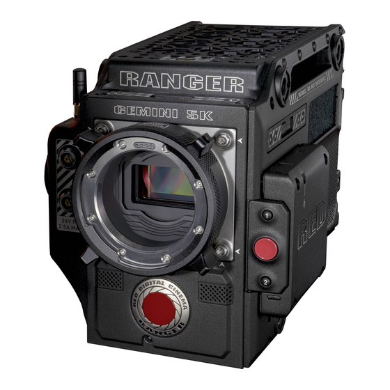
Figure: RED RANGER GEMINI RED RANGER GEMINI is an integrated 5K S35 camera system offering an all-in-one system for top-tier production use. It features all of the benefits of the GEMINI 5K S35 sensor within a compact and less complex platform for filmmakers. -
Page 9: Additional Resources
RED RANGER GEMINI OPERATION GUIDE ADDITIONAL RESOURCES The following resources offer additional information about RED, the DSMC system, and the RED community: RED.com: Check the official RED website for the latest information about RED products. RED Learn Articles: RED offers... -
Page 10: Chapter 2: Camera System Components
NOTE: Availability of components listed in this chapter is subject to change at any time. RED RANGER GEMINI CAMERA BODY This section describes the controls, buttons, and features on the RED RANGER GEMINI camera body. For information on the input/output connectors, go to Input/Output Connectors. - Page 11 RED RANGER GEMINI OPERATION GUIDE CAMERA BODY CONTROLS AND FEATURES CAMERA FRONT Figure: Camera Body Controls and Features ITEM DESCRIPTION Lens mount area Attach lens mount Mic 1 Left audio channels: Ch1 and Ch3. Go to Record and Monitor Audio Mic 2 Right audio channels: Ch2 and Ch4.
- Page 12 Figure: Camera Body Controls and Features # ITEM DESCRIPTION 7 Primary Mount a DSMC2 RED Touch LCD, LCD/EVF Adaptor A, or LCD/EVF Adaptor D EVF/LCD Port 8 Top Handle Mount the DSMC2 Top Handle or DSMC2 Outrigger Handle. This is the only mounting option for the...
- Page 13 RED RANGER GEMINI OPERATION GUIDE CAMERA LEFT Figure: Camera Body Controls and Features ITEM DESCRIPTION 10 PWR/REC button Fully press and hold the PWR/REC key for two (2) seconds to turn on/off. When the camera is on, fully press and then release the PWR/REC key to toggle record start/stop.
- Page 14 16 Focus Hook Mount the focus hook Mounting Point 17 Secondary EVF/LCD Mount a DSMC2 RED Touch LCD or LCD/EVF Adaptor D. The secondary LCD/EVF port and a Port MON-1 port cannot be used at the same time. Go to Monitor Preferences 18 Hook and loop patch Rectangle of hook and loop material for attaching labels 1.
- Page 15 Figure: Camera Body Controls and Features (shown with gold mount) ITEM DESCRIPTION 19 Battery mount Depending on the RED RANGER type, you can attach either a gold mount battery or a v-lock battery 20 Media mount Mount RED MINI-MAG media 21 Fan exhaust DO NOT block fan exhaust when the camera is on C OPYR IGH T ©...
- Page 16 RED RANGER GEMINI OPERATION GUIDE CAMERA BOTTOM Figure: Camera Body Controls and Features ITEM LOCATION DESCRIPTION Fan exhaust Back/Bottom DO NOT block fan exhaust when the camera is on Mounting Points Bottom Mount plates, tripods, monopods, etc. C OPYR IGH T © 2 0 2 0 R ED .C OM , L L C...
- Page 17 RED RANGER GEMINI OPERATION GUIDE CAMERA BODY LEDS LEFT SIDE LEDS Figure: RED RANGER LEDs, Left Side COLOR/FLASHING DESCRIPTION Power Status LED (PWR) Camera off Green Camera on Amber flashing Camera on; 5 to 10 min of battery time available...
- Page 18 RED RANGER GEMINI OPERATION GUIDE MEDIA BAY LED Figure: Media Bay LED # LED COLOR/FLASHING DESCRIPTION 1 Media Status LED (Back of media No media mounted bay) Green Preview; media mounted; > 10% of media space available Amber Record finalizing or playback mode...
- Page 19 RED RANGER GEMINI OPERATION GUIDE REC LED Figure: REC LED COLOR/FLASHING DESCRIPTION Record Status LED Not recording, or media not mounted Recording 1. For more information on how to enable/disable this LED, go to Indicator. If media is not mounted, this LED is off.
-
Page 20: Red Mini-Mag System
1. To see the Model number, go to Menu > Media > Device. 2. The RED MINI-MAG 1TB can take up to 20 seconds to mount to a computer or a camera. C OPYR IGH T © 2 0 2 0 R ED .C OM , L L C... -
Page 21: Power Components
RED RANGER GEMINI OPERATION GUIDE POWER COMPONENTS The following RED batteries, battery chargers, and power cables are compatible with the RED RANGER: ITEM PART NUMBER NOTES REDVOLT-V 740-0043 For use with V-Lock RED BRICK 740-0002 For use with V-Lock RED RANGER AC Power 740-0048 Power adaptor for AC power;... -
Page 22: Lcd/Evf Adaptors
RED EVFs, fully compatible with the RED RANGER. The DSMC2 LCD/EVF Adaptor A converts the pogo connection on the RED RANGER to a 16-Pin 1B LCD/EVF port. The DSMC2 LCD/EVF Adaptor A is designed to attach to the primary (top) EVF/LCD port on the RED RANGER. - Page 23 (side) EVF/LCD port on the RED RANGER. When used along with the DSMC2 LCD/EVF Adaptor B, this adaptor enables you to mount a DSMC2 RED Touch LCD away from the camera—to a NOGA arm or other stable mounting point.
-
Page 24: Camera Control Devices
RED RANGER GEMINI OPERATION GUIDE CAMERA CONTROL DEVICES This section describes the camera control devices that offer Record Start/Stop buttons: ITEM PART NUMBER DSMC2 Top Handle 720-0035 DSMC2 Outrigger Handle 720-0044 DSMC2 TOP HANDLE Figure: DSMC2 Top Handle Ergonomic and intuitive, the DSMC2 Top Handle was engineered entirely around the most important action for any shooter—the record button. -
Page 25: Lens Mounts
RED RANGER GEMINI OPERATION GUIDE LENS MOUNTS RED recommends only using the RED RANGER Shimmed PL Mount with the RED RANGER. Other RED lens mounts are mechanically compatible, but may cause focus accuracy issues. ITEM PART NUMBER RED RANGER Shimmed PL Mount... -
Page 26: Rails, Mounts, Tactical Gear, And Cables
RED RANGER GEMINI OPERATION GUIDE RAILS, MOUNTS, TACTICAL GEAR, AND CABLES RED offers a wide variety of support gear, mounting platforms, cables, accessories, and other equipment. For more information, visit the RED Store at www.red.com/store. MAXIMUM SUPPORTED WEIGHTS The table below lists the maximum weight each handle can support in specific configurations. Damage to handles or other components of the camera system caused by using a handle to lift more than the specified weight is not covered under warranty. -
Page 27: Chapter 3: Basic Operations
1. Any power supply connected to the DC IN port 2. Rear battery POWER CONSUMPTION The camera draws approximately 4.2 A (63 W) when configured with the DSMC2 RED Touch 7.0" LCD and RED MINI- ® 512GB. Under typical conditions batteries provide the following operating time: REDVOLT-V: Powers the camera and accessories for approximately 24 minutes. - Page 28 RED RANGER GEMINI OPERATION GUIDE TURN ON THE CAMERA NOTE: If you have just turned off the camera, wait at least three (3) seconds before turning the camera back on. 1. Attach a power source to the camera. 2. Press and release the PWR/REC key on the right side of the camera.
-
Page 29: Configure Your Camera
RED RANGER GEMINI OPERATION GUIDE CONFIGURE YOUR CAMERA This section describes common options for configuring your camera system. (missing or bad snippet) DSMC2 TOP HANDLE AND DSMC2 OUTRIGGER HANDLE: INSTALL/REMOVE INSTALL THE DSMC2 TOP HANDLE OR DSMC2 OUTRIGGER HANDLE WARNING: Before installing or removing this item, you MUST turn off the camera. - Page 30 RED RANGER GEMINI OPERATION GUIDE INSTALL THE FOCUS HOOK SCREW The camera comes with a screw stored in the bottom of the media bay, called the focus hook screw. You can install this screw in the Focus Hook Mounting point (along the sensor plane), and then pull focus from that location. You can either attach measuring tape directly to the screw, or you can install a hook to the screw, and attach the measuring tape to the hook.
-
Page 31: Shim The Red Ranger Shimmed Pl Mount
RED RANGER GEMINI OPERATION GUIDE SHIM THE RED RANGER SHIMMED PL MOUNT The RED RANGER Shimmed PL Mount is shimmed in the factory to align to the RED RANGER it is packaged with. To ® shim a RED RANGER Shimmed PL Mount, use a DENZ Flange Depth Controller (FDC), or similar tool, to measure the Flange Focal Distance (FFD). - Page 32 RED RANGER GEMINI OPERATION GUIDE OFFSET WITHOUT SHIMS SHIM 1 SHIM 2 SHIM 3 SHIM TOTAL OFFSET AFTER SHIMS INSTALL SHIMS ® REQUIRED TOOL(S): T6 TORX screwdriver, DENZ FDC (or similar tool), LOCTITE 1. Turn off the camera. 2. Use a T6 TORX driver to remove the eight (8) screws on the lock ring assembly from the PL base.
-
Page 33: Interchangeable Olpf System
RED RANGER GEMINI OPERATION GUIDE INTERCHANGEABLE OLPF SYSTEM WARNING: Read these instructions carefully and in their entirety before removing or installing an OLPF. Damage to the OLPF module, camera, or sensor due to improper handling or use is not covered under warranty. -
Page 34: Use A Tripod Or Monopod
WARNING: Ensure that the tripod, monopod, or support system is designed and rated to handle the weight of your camera configuration. RED is not responsible for any damage caused by using a tripod, monopod, mount, or support system that does not provide sufficient support. -
Page 35: Video Monitor Outputs
10-bit depth in 4:2:2 YCC or 8-bit depth in 4:4:4 RGB. The camera offers the following monitor outputs: EVF/LCD: Supports a RED EVF or LCD display. HD-SDI: Provides a 720p or 1080p output suitable for monitoring or recording to an external VTR or DDR device. It may be configured for 10-bit LIN (VIDEO) or 10-bit LOG (FILM) encoded data. -
Page 36: Record
NOTE: The secondary LCD/EVF port and a MON-1 port cannot be used at the same time. Go to Monitor Preferences. You can record simultaneously to an external recorder and a RED SSD. To record simultaneously, follow the instructions below: 1. Connect the camera to an external recorder with an HD-SDI cable. - Page 37 RED RANGER GEMINI OPERATION GUIDE EXTERNAL RECORD NOTE: The secondary LCD/EVF port and a MON-1 port cannot be used at the same time. Go to Monitor Preferences. You can record to an external recorder without recording to an SSD. To record to an external device only, follow the instructions below: 1.
-
Page 38: Chapter 4: Basic Menus And Controls
RED RANGER GEMINI OPERATION GUIDE CHAPTER 4: BASIC MENUS AND CONTROLS (missing or bad snippet) GUI MENU INTRODUCTION This section describes the structure and layout of the graphical user interface (GUI) that overlays the video monitor signal. Advanced GUI menu controls enable convenient access to menus, overlays, and other critical camera information. -
Page 39: Upper Status Row (Basic Menu)
UPPER STATUS ROW (BASIC MENU) The Upper Status Row displays basic project parameters. The currently selected parameter in the Upper Status Row is underlined with a red bar. The Upper Status Row is also known as the Basic Menu. Figure: Upper Status Row... - Page 40 RED RANGER GEMINI OPERATION GUIDE ACCESS ADVANCED MENUS For every Upper Status Row item, you can select the Advanced... button to access the related menu in the Advanced Menus. For example, select Advanced... in the Frame Rate menu to open Menu > Settings > Project > Frame Rate.
- Page 41 RED RANGER GEMINI OPERATION GUIDE FEATURE: EDIT LIST Select the Edit List... button in the Upper Status Row menus to change the values that display for each setting. For example, if you open the Frame Rate menu and select Edit List..., the camera lets you add or remove values.
-
Page 42: Live Action Area
RED RANGER GEMINI OPERATION GUIDE LIVE ACTION AREA The Live Action Area contains the recorded image area, Look Around area, and various overlays. The color of each overlay can be customized to maximize the contrast between the guide(s) and scene being captured. -
Page 43: Lower Status Row
RED RANGER GEMINI OPERATION GUIDE LOWER STATUS ROW The Lower Status Row provides access to key system information and camera values. Figure: Lower Status Row # ITEM SUB-ITEM/DESCRIPTION DETAILS 1 Camera Mode Swipe up to toggle Motion/Stills/Playback modes "Camera Mode" on the next page 2 Histogram Histogram;... - Page 44 RED RANGER GEMINI OPERATION GUIDE CAMERA MODE The Camera Mode allows you to seamlessly toggle between Motion mode, Stills mode, and Playback. To select a camera mode, select the Camera Mode icon in the Lower Status Bar, swipe up, and select a camera mode.
- Page 45 RED RANGER GEMINI OPERATION GUIDE STILLS MODE Stills mode optimizes your camera settings for capturing stills. Stills mode includes the following features: Stills recording modes: Multi-Shot Motion + Stills Swipe-Up Shortcuts: False Color Status Media Power Auto Focus Auto Exposure...
- Page 46 White Balance, ISO, and VIEW/LOOK settings 4 RAW Clip Also known as “traffic lights”. Provides a visual representation of exposure and sensor data levels for red, Meter green, and blue channels; Circles (traffic lights) will light up when clipping occurs 1.
- Page 47 The SYNC indicator shows the current sensor sync status, based on genlock. Grey: The sensor sync mode is not set to genlock. Red: The sensor sync mode is set to genlock, but is not locked to a genlock signal. This may occur if genlock or sensor sync is lost while recording.
- Page 48 NOTE: The camera turns off automatically if the supply voltage drops to 11.5 V. When using a RED battery, the power status displays the location of the power source and the remaining battery capacity. When using a RED BRICK battery connected to DC IN, the power status displays BRICK and the remaining battery capacity.
-
Page 49: Chapter 5: Sensor Calibration
The camera offers two (2) ways to calibrate the sensor: Manual Calibration: RED recommends using Manual Calibration for the HELIUM 8K S35, MONSTRO 8K VV, and GEMINI 5K S35 sensors. For more information, go to "Calibrate Sensor: Manual Calibration"... -
Page 50: Calibrate Sensor: Manual Calibration
RED RANGER GEMINI OPERATION GUIDE CALIBRATE SENSOR: MANUAL CALIBRATION The camera offers two (2) ways to calibrate the sensor: Manual Calibration and Auto Calibration. This section describes how to calibrate the sensor with Manual Calibration. When you start a Manual Calibration, the camera calibrates the sensor at the current exposure and temperature setting. - Page 51 RED RANGER GEMINI OPERATION GUIDE 8. Select OK on the dialog box that opens. The system initializes and then makes multiple passes through the following phases of the calibration: Capturing Analyzing Erasing Programming 9. When the Calibration Successful dialog displays, select OK to complete the process.
-
Page 52: Calibrate Sensor: Auto Calibration
RED RANGER GEMINI OPERATION GUIDE CALIBRATE SENSOR: AUTO CALIBRATION NOTE: The camera cannot export calibration maps created by Auto Calibration. The camera offers two (2) ways to calibrate the sensor: Manual Calibration and Auto Calibration. This section describes how to calibrate the sensor with Auto Calibration. - Page 53 RED RANGER GEMINI OPERATION GUIDE 5. Select which Sensor Sensitivity you want to calibrate at: Low Light Only: This option displays when the current Sensor Sensitivity is Low Light. Standard Only: This option displays when the current Sensor Sensitivity is Standard.
-
Page 54: Calibration Map Naming Conventions
RED RANGER GEMINI OPERATION GUIDE CALIBRATION MAP NAMING CONVENTIONS All calibration maps for Low Light Sensor Sensitivity are marked with the "LL" symbol. Each calibration map has a unique name that uses the format described in the table below: NAME... -
Page 55: Calibration Management
RED RANGER GEMINI OPERATION GUIDE CALIBRATION MANAGEMENT To apply, export, and import calibration maps, go to Menu > Settings > Maintenance > Calibrate > Sensor. In Camera: The calibration maps that are saved internally on the camera: Factory: This is the calibration map generated during the manufacturing process. (Default) All other: The user-created calibration maps. -
Page 56: Chapter 6: Upgrade Camera Firmware
NOTE: On Mac computers with REDCINE-X PRO installed, RED Watchdog mounts the SSD as Read-Only by default, which means that you are unable to write files (including firmware upgrade files) to the SSD. Change the Mount preference to Read-Write before attempting to copy firmware to the SSD. - Page 57 9. After the camera turns off, remove the SSD and wait 10 seconds. 10. Turn on the camera. The camera may take 30 seconds or longer to upgrade all of the attached RED devices. During this time the PWR and REC LEDs flash green and nothing displays on the external monitors.
-
Page 58: Chapter 7: Camera System Maintenance
Clean with a dry lint-free cloth. When cleaning your camera and accessories, remember that the devices are not waterproof and moisture can damage electronic circuitry. STORAGE RED recommends that you store the camera and accessories in the water-resistant cases available in the RED Store www.red.com/store. These cases feature laser-cut foam to keep the camera and accessories secure. -
Page 59: Clean Evf Screen
DSMC2 RED EVF Modular Optical Block. Use an ionized rubber air bulb to clean the screen on the DSMC2 RED EVF. If there are still particles on the screen after using an air bulb, gently wipe the screen with a rolled-up, particulate-free, non-abrasive optical-grade wipe. -
Page 60: Water Damage
Cleaning the screen without removing solid particles increases the risk of scratching the screen. PROHIBITED LCD SCREEN CLEANERS DO NOT use any of the items listed below to clean LCD screens. These products have not been tested on RED products and may cause damage or streaking. Compressed air... -
Page 61: Chapter 8: Troubleshoot Your Camera
SSDs. 10. If any errors occur, save a log file and submit a Support ticket at https://support.red.com. NOTE: Problems or dropped frames found during the stress test display as “Errors” in the bottom of the user interface. - Page 62 RED RANGER GEMINI OPERATION GUIDE GENERAL: LENS MOUNT NOT FUNCTIONING SYMPTOM The lens mount is not functioning correctly, or is not communicating with the camera. POTENTIAL RESOLUTIONS Perform a Hardware Rediscover. For more information, go to Rediscover (Hardware Rediscover). Upgrade your camera firmware. For more information, go to "Upgrade Camera Firmware"...
- Page 63 RED RANGER GEMINI OPERATION GUIDE SCREEN FREEZES OR DOES NOT DISPLAY SYMPTOM The screen freezes or does not display. POTENTIAL RESOLUTION Perform a Hard Restore. For more information, go to "Perform a Hard Restore" on page INTERMITTENT MOTION JITTER SYMPTOM A slight, intermittent motion jitter displays on the monitor.
- Page 64 RED RANGER GEMINI OPERATION GUIDE CANNOT USE TOUCHSCREEN SYMPTOM Cannot control the camera via the touchscreen or the Side LCD. POTENTIAL RESOLUTIONS Perform a Hard Restore. For more information, go to "Perform a Hard Restore" on the next page. If you are using an external monitor, enable menus on the monitors and control the camera via the Side LCD: ®...
- Page 65 RED RANGER GEMINI OPERATION GUIDE PERFORM A HARD RESTORE A common way to resolve camera firmware issues is to perform a Hard Restore. A Hard Restore functions like a System Restore in that it changes all settings to the factory default values.
- Page 66 RED RANGER GEMINI OPERATION GUIDE TIMECODE OR GENLOCK DOES NOT FUNCTION SYMPTOM The SYNC, GEN, and/or TC light is red, yellow, or greyed out. POTENTIAL RESOLUTIONS Ensure that your timecode or genlock device is compatible. For more information, go to...
- Page 67 RED RANGER GEMINI OPERATION GUIDE NO MON-1 SIGNAL SYMPTOM The MON-1 port does not output a signal. EXPLANATION The secondary LCD/EVF port (on the side of the camera) and the MON-1 port cannot be used at the same time. For...
-
Page 68: Error Messages
POTENTIAL RESOLUTIONS Update the camera firmware to the latest release build available for download at www.red.com/downloads. Submit a Support ticket at https://support.red.com. Include the following with the request: Log file. For more information, go to Save Log. List of devices, lens, and third-party accessories that were attached when the error occurred. - Page 69 Error 0x00000020. Please save log and send to RED Support. ERROR 0x20. Media integrity error. Please secure format the SSD. If the issue persists, save log file and contact RED Support with the log file, method of powering camera, and camera configuration. POTENTIAL RESOLUTIONS Perform a secure format of the SSD.
- Page 70 SYMPTOM The display shows the following message: "Media integrity error. Please secure format the SSD. If the issue persists, save log file and contact RED Support with the log file, method of powering camera, and camera configuration." POTENTIAL RESOLUTIONS Perform a secure format of the SSD. For more information, see the...
- Page 71 Select a different recording file format and/or resolution from the Codec menu. For more information, go to Select Record File Format. Submit a Support ticket at https://support.red.com. Include the following with the request: Log file. For more information, go to Save Log.
-
Page 72: Appendix A: Technical Specifications
Max Data Rates Up to 300 MB/s using RED MINI-MAG (480GB, 512GB, 960GB & 1TB) Up to 225 MB/s using RED MINI-MAG (120GB & 240GB) Max Frame Rates 75 fps at 5K Full Height 1.7:1 (5120 x 3000) 96 fps at 5K Full Format (5120 x 2700), 120 fps at 5K 2.4:1 (5120 x 2160) 120 fps at 4K Full Format (4096 x 2160), 150 fps at 4K 2.4:1 (4096 x 1728) - Page 73 7.0" LCD, and DSMC2 RED EVF (OLED) with cable-free connection. RED Touch 9.0" LCD, RED Touch 7.0" LCD, RED Touch 5.0" LCD, RED PRO 7" LCD, DSMC2 Touch 7.0" Ultra-Brite LCD, BOMB EVF (OLED) and BOMB EVF (LCOS) compatible with DSMC2 LCD/EVF Adaptor A or DSMC2 LCD/EVF Adaptor D, and LCD/EVF cable.
-
Page 74: Appendix B: Mechanical Drawings
RED RANGER GEMINI OPERATION GUIDE APPENDIX B: MECHANICAL DRAWINGS RED RANGER GEMINI WITH V-LOCK NOTE: Dimensions are shown in mm. The optical axis height of the camera is 95.90 mm. FRONT VIEW Figure: Camera Front View C OPYR IGH T © 2 0 2 0 R ED .C OM , L L C... - Page 75 RED RANGER GEMINI OPERATION GUIDE BACK VIEW Figure: Camera Back View C OPYR IGH T © 2 0 2 0 R ED .C OM , L L C 9 5 5 - 0 1 9 2 _ V7 .3 , R EV- A...
- Page 76 RED RANGER GEMINI OPERATION GUIDE SIDE VIEW (RIGHT) Figure: Camera Side View (Right) C OPYR IGH T © 2 0 2 0 R ED .C OM , L L C 9 5 5 - 0 1 9 2 _ V7 .3 , R EV- A...
- Page 77 RED RANGER GEMINI OPERATION GUIDE SIDE VIEW (LEFT) Figure: Camera Side View (Left) C OPYR IGH T © 2 0 2 0 R ED .C OM , L L C 9 5 5 - 0 1 9 2 _ V7 .3 , R EV- A...
- Page 78 RED RANGER GEMINI OPERATION GUIDE TOP VIEW Figure: Camera Top View C OPYR IGH T © 2 0 2 0 R ED .C OM , L L C 9 5 5 - 0 1 9 2 _ V7 .3 , R EV- A...
- Page 79 RED RANGER GEMINI OPERATION GUIDE BOTTOM VIEW Figure: Camera Bottom View C OPYR IGH T © 2 0 2 0 R ED .C OM , L L C 9 5 5 - 0 1 9 2 _ V7 .3 , R EV- A...
-
Page 80: Red Ranger Gemini With Gold Mount
RED RANGER GEMINI OPERATION GUIDE RED RANGER GEMINI WITH GOLD MOUNT NOTE: Dimensions are shown in mm. The optical axis height of the camera is 95.90 mm. FRONT VIEW Figure: Camera Front View C OPYR IGH T © 2 0 2 0 R ED .C OM , L L C... - Page 81 RED RANGER GEMINI OPERATION GUIDE BACK VIEW Figure: Camera Back View C OPYR IGH T © 2 0 2 0 R ED .C OM , L L C 9 5 5 - 0 1 9 2 _ V7 .3 , R EV- A...
- Page 82 RED RANGER GEMINI OPERATION GUIDE SIDE VIEW (RIGHT) Figure: Camera Side View (Right) C OPYR IGH T © 2 0 2 0 R ED .C OM , L L C 9 5 5 - 0 1 9 2 _ V7 .3 , R EV- A...
- Page 83 RED RANGER GEMINI OPERATION GUIDE SIDE VIEW (LEFT) Figure: Camera Side View (Left) C OPYR IGH T © 2 0 2 0 R ED .C OM , L L C 9 5 5 - 0 1 9 2 _ V7 .3 , R EV- A...
- Page 84 RED RANGER GEMINI OPERATION GUIDE TOP VIEW Figure: Camera Top View C OPYR IGH T © 2 0 2 0 R ED .C OM , L L C 9 5 5 - 0 1 9 2 _ V7 .3 , R EV- A...
- Page 85 RED RANGER GEMINI OPERATION GUIDE BOTTOM VIEW Figure: Camera Bottom View C OPYR IGH T © 2 0 2 0 R ED .C OM , L L C 9 5 5 - 0 1 9 2 _ V7 .3 , R EV- A...
-
Page 86: Appendix C: Lens Mounts And Lenses
This section describes camera lens mounts. Camera mounts may be configured with 19mm rods to accommodate most cinematography lenses, matte boxes, and follow focus systems. RED recommends only using the RED RANGER Shimmed PL Mount with the RED RANGER. Other RED lens mounts are mechanically compatible, but may cause focus accuracy issues. - Page 87 RED RANGER GEMINI OPERATION GUIDE INSTALL A LENS MOUNT NOTE: You can change lens mounts in the field. However, RED recommends that you change lens mounts only in a dust-free environment. REQUIRED TOOL(S): T20 TORX driver 1. Ensure that the camera is turned off and remove any accessories or cables that may interfere with installation.
-
Page 88: Lenses
RED RANGER GEMINI OPERATION GUIDE LENSES This section describes lenses that are compatible with the RED RANGER Shimmed PL Mount. Other lenses and lens mounts may be used with the RED RANGER, but may cause focus accuracy issues. To avoid vignetting, use standard full frame PL mount lenses. - Page 89 In the camera, go to Menu > Settings > Setup > Lens, and select the Enable Power to Lens check box. RED recommends using an external battery for the lens, since the lens mount provides a limited supply of power to the lens.
Need help?
Do you have a question about the RANGER GEMINI 5K S35 and is the answer not in the manual?
Questions and answers