Sign In
Upload
Manuals
Brands
JUKI Manuals
Sewing Machine
AMS-221ENHL
JUKI AMS-221ENHL Manuals
Manuals and User Guides for JUKI AMS-221ENHL. We have
1
JUKI AMS-221ENHL manual available for free PDF download: Engineer's Manual
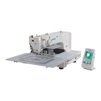
JUKI AMS-221ENHL Engineer's Manual (253 pages)
Computer-controlled, Cycle Machine With Input Function
Brand:
JUKI
| Category:
Sewing Machine
| Size: 5.63 MB
Table of Contents
Table of Contents
3
1 Specifications
5
2 Configuration
6
Names of Main Unit
6
Operation Panel
7
3 Standard Adjustment
8
Adjustment of the Throat Plate Auxiliary Cover Height
8
Adjustment of the Feed Bar Auxiliary Cover Rail X
10
Adjustment of the X Movement Top Cover
10
Main Shaft Connection/Disconnection
12
Removal of Main Shaft Motor and Coupling
14
Crank Rod Connection/Disconnection
16
Crank Balancer Positioning
18
Adjustment of Intermediate Presser Cam
20
Adjustment of Intermediate Presser Bar
20
Intermediate Presser Variable Connection/Disconnection
22
Intermediate Presser Variable Adjustments
24
Intermediate Presser Drive Arm
26
Lower Shaft Backlash Adjustment and Connection/Disconnection
28
Oscillator Gear Positioning
28
Adjustment of Hook Oil Amount
30
Shuttle Connection / Disconnection and Oil Wick Piping
30
Adjusting the Height of the Needle Bar
32
Hook Adjustment
34
Thread Trimmer Presser Lifter Cam Connection/Disconnection
36
Thread Trimmer and Presser Origin Sensor Adjustment
36
Adjustment of the Moving Knife and Counter Knife Position
38
Floating Amount of the Thread Tension Disk
38
Second Thread Tension Connection / Disconnection
40
AT Unit Connection / Disconnection
42
Wiper Adjustment
44
Backlash Adjustment for the X Motor
46
Backlash Adjustment for the y Motor
46
Adjustment of the Tension of the X Timing Belt
48
Adjustment of the Tension of the y Timing Belt
50
How to Remove Rattles from the y Drive Shaft
52
Phase Adjustment for the y Timing Belt
52
Adjustment of the X-Y Mechanism
54
Pressure Adjustment for the Side Plate Bearing
56
Initial Length of the Presser Cylinder
58
Initial Length of the 2-Step Stroke Cylinder
58
Adjustment of the Speed Controller
60
Adjustment of the Pressure Reducer
62
Making the Origin Setting Gauge
64
Adjusting the X Origin Sensor
64
Adjusting the y Origin Sensor
66
Adjustment of the Bobbin Winder Driving Wheel Position
68
Adjusting the Bobbin Winder Amount
68
Adjustment of the Shuttle Upper Spring and Lower Thread Holder Position
70
Shuttle Felt
70
Shape of the Shuttle Race Ring
72
Adjustment of Thread Take-Up Spring
72
Needle Thread Clamp Device Connection/Disconnection
74
Adjusting the Needle Thread Clamp Notch
76
Adjusting the Needle Thread Clamp Sensor
78
Adjustment of Tilt Machanism of the Machine Head
80
4 Memory Switch
86
Start and Change
86
Function List
87
5 Supplemental Remarks of each Function Number and Explanation of each Function
104
Feeding Frame Operational Sequence Setup
104
Fixed Refuge Position Setup
108
Bank Function Setup
109
Port I/O Setup
112
Simplified Program Setup
125
Version Display
138
Keylock Setup
139
Customize Function Setting of Key Lock
141
Communication Screens of the Maintenance Personnel Level (Program Rewrite)
148
Information Screen at the Maintenance Personnel Level
152
Test Sewing Function
154
6 Test Mode
157
7 Printed Wiring Board and Dip Switch
173
Various Printed Wiring Boards
173
Dipswitch Setup
181
8 Table of Exchanging Gauge Parts According to Sewing Specifications and Needle Size Used
182
9 Option List
183
Method of Pedal Switch Cable Set Connections
190
10 Maintenance
192
Replacing the Fuse
192
Changing the Voltage Specification
193
Greasing• Lock-Tight Parts
194
Parts to Which Grease • Locktight Is Applied
195
Replenishing the Designated Places with Grease
204
11 Error Code List
209
12 Message List
217
13 Troubles and Corrective Measures
221
Mechanical Parts
221
Sewing Conditions
225
Electrical Components
234
14 Circuit Diagrams
243
Block Diagram
243
Power Supply Circuit Diagram a
244
Power Supply Circuit Diagram B
245
Power Supply Circuit Diagram C
246
Servo Motor Circuit Diagram
247
Sensor-Pedal Circuit Diagram
248
MAIN•PANEL Board Circuit Diagram
249
Motor•Solenoid Circuit Diagram
250
Air System Circuit Diagram
251
15 Drawing of the Table
252
Advertisement
Advertisement
Related Products
JUKI AMS-221EN-HS2516
JUKI AMS-221EN-HL2516
JUKI AMS-221EN-HS3020
JUKI AMS-221ENHS
JUKI AMS-221EN-HS3020/7200
JUKI AMS-221EN/IP-420
JUKI AMS-221EN-SS2516
JUKI AMS-221EN-SL2516
JUKI AMS-221ENSS
JUKI AMS-221ENSL
JUKI Categories
Sewing Machine
Industrial Equipment
Sewing Machine Accessories
Accessories
Printer
More JUKI Manuals
Login
Sign In
OR
Sign in with Facebook
Sign in with Google
Upload manual
Upload from disk
Upload from URL