Advertisement
Quick Links
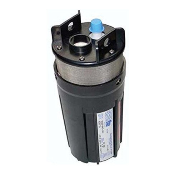
9325 SERIES
12/24 VDC POWERED
SUBMERSIBLE PUMP
OWNERS MANUAL
WARNING
DO NOT use any SHURflo pump for petrol/gasoline,
petroleum products, solvents, thinners or ANY other
flammable liquid with flash point below 180 F [82 C].
NOT FOR USE where flammable vapors are present.
Note:
BEFORE CONNECTING OR OPERATING
THIS PRODUCT, PLEASE READ THESE
INSTRUCTIONS COMPLETELY.
Advertisement

Related Manuals for Pentair SHURflo 9325 Series


Summary of Contents for Pentair SHURflo 9325 Series
- Page 1 9325 SERIES 12/24 VDC POWERED SUBMERSIBLE PUMP OWNERS MANUAL WARNING DO NOT use any SHURflo pump for petrol/gasoline, petroleum products, solvents, thinners or ANY other flammable liquid with flash point below 180 F [82 C]. NOT FOR USE where flammable vapors are present. Note: BEFORE CONNECTING OR OPERATING THIS PRODUCT, PLEASE READ THESE...
- Page 2 INTRODUCTION This manual has been provided as an aid to the operator with information about installing, operating, and servicing of the SHURflo 9325 Series Submersible Pump. The engineers and technicians who designed and manufactured these pumps have developed these instructions from their experiences.
- Page 3 APPLICATION WORKSHEET Please fill in for your records. PUMP DISTRIBUTOR: MODEL NUMBER_____________________________ SERIAL NUMBER_____________________________ Name_______________________________________________________ MFG. DATE_________________________________ Address______________________________________________________ PURCHASE DATE_____________________________ City_________________________________________________________ TOTAL WELL DEPTH_________________FT(M) Phone_______________________________________________________ WELL RECOVERY RATE____________________________________________________________________________________________ SOLAR ARRAY INFORMATION: MAKE/MODEL___________________________________________________________________________________________________ WATTS AVAILABLE __________________________________________________________________ (NO. OF PANELS X WATTS PER PANEL= ) CONTROLLER INFORMATION: MAKE/MODEL___________________________________________________________________________________________________ NOTE: Use of an LCB (Linear Current Booster) Unit is required for optimum performance.
- Page 4 PUMP FLOW TABLES - TOTAL VERTICAL LIFT= H1+H2+H3 12 VDC FLOW TABLE TOTAL FLOW RATE SOLAR ARRAY SIZE CURRENT VERTICAL MINIMUM TOTAL AMPS LIFT HOUR POWER RATING FEET METERS GAL WATTS 12.2 18.3 24.4 30.5 36.6 42.7 48.8 54.9 61.0 70.1 24 VDC FLOW TABLE TOTAL...
- Page 5 I. PUMP CONNECTION & INSTALLATION INSTRUCTIONS WARNING: IMPROPER INSTALLATION WILL VOID WARRANTY. Select and Purchase the Proper Jacketed Cable (Fig. 1) Note: DO NOT select cables with irregular shapes, rough or grooved surfaces. A smooth jacket is needed for proper sealing. Use a #10 AWG jacketed Submersible Cable that fits into the general size requirements shown (Fig 1).
- Page 6 PUMP CONNECTION & INSTALLATION INSTRUCTIONS (Continued) Insert the wire leads into Plug (Cable Adapter) connectors and use a 5/64" Allen Wrench to tighten the set screws (Fig. 6). Either wire can go into either plug hole. Pump performance will be the same. Slide the Inner Cable Boot (B) over the plug until it is flush with the first step on the collar (Fig.
- Page 7 PUMP CONNECTION & INSTALLATION INSTRUCTIONS (Continued) Notes: Prior to installing the pump, fill in the Application Worksheet on page 3. The Application Worksheet is a guide to make sure that the pump is installed properly in the well. Following the guidelines laid out in the Application Worksheet will allow the pump to perform efficiently and extend the life of the unit.
- Page 8 TROUBLESHOOTING SYMPTOM POSSIBLE CAUSE CORRECTION PUMP OPERATES: NO FLOW or 1. LOW VOLTAGE 1. CHECK POWER SUPPLY FOR PROPER VOLTAGE. REDUCED FLOW REFER TO TECHNICAL SPECIFICATIONS 2. NO WATER AT PUMP 2. MAKE SURE THE PUMP IS INSTALLED BELOW THE LOWEST ANTICIPATED WATER LEVEL REFER TO INSTALLATION SECTION 3.
- Page 9 II. PUMP REMOVAL AND DISASSEMBLY Warning: Make sure all electrical power is off and the Hose (Pipe) is not under pressure. Warning: Canister may be pressurized. Disassemble the pump in proper order. Follow the directions carefully. Note: Keep all of the parts clean after disassembly. Upper Housing Assembly contains small parts. Be careful not to lose parts after removing Upper Housing (N) in step 9.
- Page 10 PUMP REMOVAL AND DISASSEMBLY (CONTINUED) 9. Remove Upper Housing (N) and Motor (T) (Fig. 11) Note: Keep all parts clean after disassembly. The Upper Housing Assembly contains small parts. Be careful not to lose parts after removing Upper Housing. Use a 5/32" Allen Wrench to remove the 3 screws (L). Before separating the Upper Housing (N) from the Motor (T), place the assembly with the Upper Housing (N) down and the Motor (T) facing up.
- Page 11 III. PUMP RE-ASSEMBLY Warning The Order of Assembly is important for proper sealing. 1. Install the Upper Housing Large O-Rings (O) (Fig. 11 & 12) Remove the existing Large O-Rings and thoroughly clean the O-Ring grooves with a dry cloth and a cotton tipped applicator. Note: Lubricate the O-Rings with the Supplied O-Ring Grease.
- Page 12 PUMP RE-ASSEMBLY (Continued) Install the Canister (U) (Fig. 13) Clean the inside of the Canister with a dry cloth. Align the wire channel in the canister with the motor lead wires. Slide the canister over the entire assembly . Twist the canister to align the screw holes and carefully press on the bottom end to seat properly.
- Page 13 PUMP RE-ASSEMBLY (Continued) Install the Filter Screen (M) (Fig. 16) 11.1 Slide the Filter Screen (M) onto the Upper Housing (N). 11.2 Align the slots in the Filter Screen (M) with the screws (V) in the Upper Housing (N) and slide the Filter Screen (M) over the screws (V). Install the Outlet Fitting (G) (Fig.
- Page 14 SPECIFICATIONS MODEL NUMBER: 9325-043-101 PUMP DESIGN: Positive Displacement 3 Chamber Diaphragm Pump CAM: 3.0 Degree MOTOR: Permanent Magnet, P/N 11-175-00 Thermally protected VOLTAGE: 24 VDC Nominal (Reduced Volume @ 12VDC) WATTS: 120W AMPS: 4.0 MAX FUSE: 7.5 AMP (Automotive) Not Included 3.75 in.
- Page 15 MODEL 9325 SUBMERSIBLE PUMP PARTS LIST – Refer to FIGURE 17 ITEM DESCRIPTION QUANTITY CABLE [NOT INCLUDED] INNER CABLE BOOT OUTER CABLE BOOT PLUG (CABLE ADAPTER) [NOT SHOWN] SCREW (PLUG) [NOT SHOWN] SCREW (LIFT PLATE) LIFT PLATE OUTLET FITTING O-RING (OUTLET FITTING) O-RING (LIFT PLATE) RECEPTACLE (CABLE ADAPTER) SET SCREW (RECEPTACLE)
- Page 16 VIEW A VIE W B FIGURE 17...
- Page 17 Pentair Water Belgium bvba, Industriepark Wolfstee, Toekomstlaan 30, B-2200 Herentals, Belgium, +32-14-283500 All Pentair trademarks and logos are owned by Pentair, Inc. All other brand or product names are trademarks or registered marks of their respective owners. Because we are continuously improving our products and services, Pentair reserves the right to change specifications without prior notice.
Need help?
Do you have a question about the SHURflo 9325 Series and is the answer not in the manual?
Questions and answers