Pentair HYPRO 9306C Series Installation And Operation Manual
Cast iron & stainless steel series
Hide thumbs
Also See for HYPRO 9306C Series:

Related Manuals for Pentair HYPRO 9306C Series


Summary of Contents for Pentair HYPRO 9306C Series
- Page 1 KEEP FOR FUTURE REFERENCE CAST IRON & STAINLESS STEEL SERIES 9306C 9306S INSTALLATION AND OPERATION MANUAL pentair.com...
-
Page 2: Table Of Contents
Contents EU Language Manuals................................3 Introduction.................................4 Description..............................4 Intended Uses................................4 Purpose of Manual..............................4 Misuses................................5 Pump Identification..............................5 Pump Technical Data................................6 Fluid Pumping Applications............................10 Tools................................10 Lifting, Transport, and Intermediate Storage.......................10 Assembly and Installation..............................11 Assembly............................11 Installation...........................11 Control Systems...............................13 Commissioning Start-Up, Operation, Shutdown........................14 Information.............................14 Start-Up, Operation, Shutdown..........................14 Maintenance and Servicing..............................16 Information..........................16 D i s p o s a l . -
Page 3: Eu Language Manuals
EU Language Manuals DO NOT attempt to install or operate your pump before reading the manual. Original copies of the manual for Hypro pumps are provided in English. To find a copy in your native language, go to www.hypropumps.com. Vor dem Ablesen des Handbuches versuchen Sie NICHT, Ihre Pumpe zu installieren. Originale des Handbuches fur Hypro-Pumpen werden auf englisch zur Verfugung gestellt. Zu eine Kopie in Ihrer Muttersprache finden, zu www.hypropumps.com zu gehen (German) N’essayez pas d’installer votre pompe avant de lire le manuel. -
Page 4: Introduction
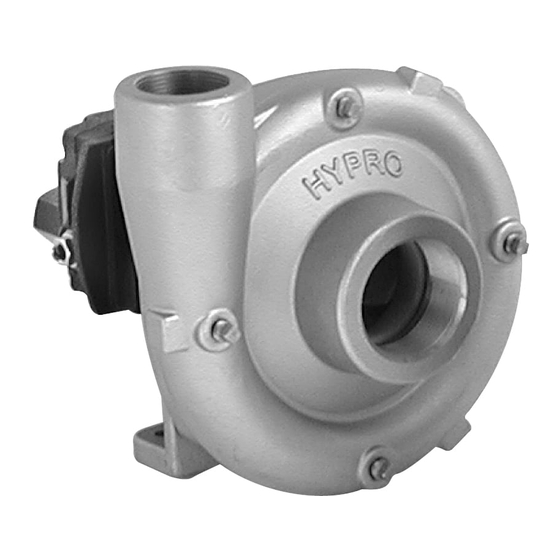
Introduction Description Hypro centrifugal pumps are designed for creating and boosting pressure in fluid circuits. The pump operates by taking in fluid from the inlet port after which it is slung by the impeller and expelled through the outlet port. Construction features include housings, impellers and seals which come in a variety of materials in order to be resistant to a range of chemicals. Standard models of centrifugal pumps rotate clockwise, when looking at the shaft end of the pump. Intended Uses Hypro centrifugal pumps are intended for creating or boosting dynamic pressure in approved fluids. Hypro centrifugal pumps should never be used to pump liquids above 140°F (60°C), or below 34°F (1°C). For pumps equipped with hydraulic motors, the pump should not be run if the hydraulic oil temperature exceeds 135°F (57°C). -
Page 5: Misuses
Misuses Hypro centrifugal pumps are designed to operate effectively within the specified speed, pressure and environmental ranges. Going outside of these ranges will void the warranty and could cause damage to property, serious injury, or death. • DO NOT run the pump faster than the maximum specified speed. • DO NOT run the pump higher than the maximum specified pressure. • DO NOT run pumps when the liquid has exceeded the maximum or minimum temperature limit (see Intended Uses). • DO NOT pump non-approved liquids. • DO NOT pump water or other liquids for human consumption. •... -
Page 6: Pump Technical Data
Pump Technical Data (All specifications and performance data are based on water as a carrier fluid.) 9306C(S)-HM1C, -HM3C, and -HM5C Pump Dimensions Dim. Inch 8.56 217.4 9.33 237.0 HM1,3,5 5.19 131.8 3.81 96.8 3.88 96.8 11.78 299.2 12.28 311.9 11.90 302.3 5.03 127.8 5.25 133.4 HM1,3,5 2.63 66.8 1.91 48.5 9306C(S)-HM1C-3U, -HM3C-3U, and -HM5C-3U Pump Dimensions Dim. - Page 7 Pump Technical Data 9306C-HM1C, 9306S-HM1C, 9306C-HM3C, 9306S-HM3C, 9306C-HM5C, 9306S-HM5C Pump Specifications Max Hyd Hydraulic Max Flow Pressure Flow Max PSI Rate (GPM) (PSI) (GPM) Hydraulic Mounting Pump [BAR] [LPM] [BAR] [LPM] Ports Ports Weight Bolts 9306C-HM1C 207 [783.6] 130 [8.9] 13 [49.2] 9306S-HM1C 214 [810]...
- Page 8 12 GPM 11 GPM Pump Technical Data Performance Charts 9306C-HM1C & 9306S-HM1C 9306C-HM1C & 9306S-HM1C METRIC 9306C-HM1C & 9306S-HM1C 9306C-HM1C & 9306S-HM1C METRIC 9306C-HM1C-U and 9306S-HM1C-U 9306C-HM1C-U and 9306S-HM1C-U 9306C-HM1C-U and 9306S-HM1C-U 9306C-HM1C-U and 9306S-HM1C-U 49.2 LPM 45.4 LPM ...
- Page 9 Pump Technical Data Performance Charts 9306C-HM1C-3U & 9306S-HM1C-3U 9306C-HM1C-3U & 9306S-HM1C-3U METRIC 9303C-HM1C-3U & 9306S-HM1C-3U METRIC 9306C-HM1C-3U & 9306S-HM1C-3U 49.2 LPM 13 GPM 12 GPM 45.4 LPM 11 GPM 41.6 LPM 1000 1200 9306C-HM3C-3U & 9306S-HM3C-3U 9306C-HM3C-3U &...
-
Page 10: Fluid Pumping Applications
Fluid Pumping Applications Pump Materials Compatibility Application Impeller Pump Housing Seal Nylon Polypropylene Stainless Cast Iron Ceramic Silicon Carbide Weed Control Chemicals Insect Control Brush Control Pest Control Chemicals and Fumigants Liquid Fertilizers Powdered Fertilizers Fluid Transfer Acids Table 1 Flammable liquids, sewage, and clean water should never be pumped through a Hypro pump. Hypro pumps are not designed to be used as clean water pumps as defined in 10CFR Parts 429 and 431. -
Page 11: Assembly And Installation
Figure 1 Transport • All Hypro pumps are capable of being transported by air, sea, rail or motor vehicle. When the pump is shipped, ensure that the pump is moved in accordance with local and national laws and is properly secured to prevent unwanted movement which could cause damage to person or property. Prior to shipping, all fluids should be removed from the pump. - Page 12 • Installers must provide hydraulic components that are capable of withstanding maximum source pressure. • The working pressure must be controlled by a pressure relief valve that is adjusted to operate at a maximum pressure of the hydraulic motor. • For pumps with gas engines, the exhaust must be directed away from operators and anyone standing nearby to ensure that exhaust fumes do not enter their breathing zone.
-
Page 13: Control Systems
Hydraulic Installation • When installing the hydraulic motor into the tractor or sprayer’s hydraulic system, make sure that no dirt or liquid gets into the hydraulic motor. KEEP ALL HYDRAULIC CONNECTIONS CLEAN. • Ensure return line is connected to low pressure return port on the tractor recommended for hydraulic motors, the ports are identified on the motor casting. Hydraulic supply lines should be at least the same size as the hydraulic motor port or larger. • Standard models come equipped with check valve port adapters which should not be removed. Hooking up the motor in the wrong direction will damage the hydraulic seal. Control Systems •... -
Page 14: Commissioning Start-Up, Operation, Shutdown
Commissioning, Start-Up, Operation, Shutdown Before attempting to start your pump, the following must be understood and followed to ensure safe operation. Information • When running Hypro centrifugal pumps, it is essential that operators use hearing protection as the sound levels can reach levels of 80 decibels. • When handling Hypro pumps, one should wear steel-toed shoes and protective gloves in order to protect the feet in the event the pump is dropped and protect the hands from any sharp surfaces on the pump or chemicals. - Page 15 Priming the Pump To help prime the pump, keep the inlet or suction line as short as possible with a minimum of bends, elbows and kinks. Make sure all connections are tight and do not leak air. Non self-priming pumps must have the inlet line and pump flooded with liquid before starting the pump. For self-priming models, the front chamber should be filled with liquid before starting. Starting, Operation and Shutdown of the Pump (Hydraulic) Open Center Systems - All Models Adjusting Centrifugal Pump Output ATTENTION HM1C, HM3C & HM5C motors have bypass screw fully closed from the factory. HM2C & HM4C motors have bypass screw set at 1-1/2 turns from fully closed from the factory.
-
Page 16: Maintenance And Servicing
Maintenance and Servicing Information • All maintenance should be done when machinery is stationary and has been isolated from its energy sources. It is dangerous to perform maintenance while machinery is still connected to its power source. Machinery should be isolated from its electrical, hydraulic or gas engine power source. -
Page 17: Maintenance, Routine Servicing, And Inspection
Maintenance, Routine Servicing, and Inspection PREVENTATIVE MAINTENANCE CHECKLIST Check Daily Weekly Water Leaks Plumbing • Each system’s maintenance cycle will be exclusive. If system performance decreases, check immediately. • Duty cycle, temperature, quality, type of fluid being pumped, and inlet feed conditions all affect the life of spray boom assemblies and service cycle. Troubleshooting Before attempting to service your pump, be sure that it is disconnected from all energy sources. Symptom Probable Cause(s) Corrective Action Pump does not prime Leak in suction line Check hose and fittings for leaks and correct Obstruction in suction line Inspect hose for obstructions and remove Suction hose stuck to tank Cut a notch or “V”... -
Page 18: Replacement Parts
Replacement Parts The following drawings show the pumps and their replacement parts. Only genuine replacement parts should be used. Failure to follow this warning can result in damage to property, serious injury or death. If the pump malfunctions or is defective, it should be sent back to Hypro for service. 9306C(S)-HM1, 3, 5C and 9306C(S)-HM1, 3, 5C-3U NOTE: When ordering parts, give QUANTITY, PART... -
Page 19: Declaration Of Incorporation
EC DECLARATION OF INCORPORATION EC Declaration of Incorporation Manufacturers Name: Pentair Flow Technologies, LLC Manufacturers’ Address: 375 Fifth Avenue NW, New Brighton, MN 55112, USA Declare that the partially complete machinery described below conforms to applicable health and safety requirements of Emission Directive 2010/26/EU and of Parts 1 of Annex I of Machinery Directive 2006/42/EC. - Page 20 Check with your shipping company for specific instructions. For a detailed list of where Pentair trademarks are registered, please visit www.pentair.com/en/registrations.html. Pentair trademarks and logos are owned by Pentair PLC. or its affiliates. Third party registered and unregistered trademarks and logos are the property of their respective owners. Because we are continuously improving our products and services, Pentair reserves the right to change specifications without prior notice.
Need help?
Do you have a question about the HYPRO 9306C Series and is the answer not in the manual?
Questions and answers