Table of Contents
Advertisement
Quick Links
CAME UNITED KINGDOM LTD
UNIT 3,
ORCHARD PARK INDUSTRIAL ESTATE,
TOWN STREET, SANDIACRE,
NOTTINGHAM NG10 5BP
TEL: 0115 921 0430
FAX: 0115 921 0431
INTERNET - www.cameuk.com
E-MAIL - enquiries@cameuk.com
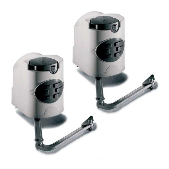
FAST-P, Pair of gates automation kit
Kit consists of :
2 x fast motors 240V
1 x built-in control panel 240V
1 x radio receiver
1 x tuned antenna
2 x remote control handsets
1 x pair safety photocells
1 x flashing "in movement" light
Full installation guide
UNITED KINGDOM LTD.
FAST-S, Single gate automation kit
Kit consists of :
1 x fast motor 240V
1 x built-in control panel 240V
1 x radio receiver
1 x tuned antenna
2 x remote control handsets
1 x pair safety photocells
1 x flashing "in movement" light
Full installation guide
TECHNICAL
HELPLINE
0115 921 0430
Advertisement
Table of Contents

Related Manuals for CAME FAST KIT


Summary of Contents for CAME FAST KIT
- Page 1 CAME UNITED KINGDOM LTD UNIT 3, ORCHARD PARK INDUSTRIAL ESTATE, TECHNICAL TOWN STREET, SANDIACRE, NOTTINGHAM NG10 5BP HELPLINE TEL: 0115 921 0430 0115 921 0430 FAX: 0115 921 0431 INTERNET - www.cameuk.com E-MAIL - enquiries@cameuk.com UNITED KINGDOM LTD. FAST-P, Pair of gates automation kit...
- Page 2 INTRODUCTION These instructions will show you how to install a FAST gate kit to a pair of gates. Please read these instructions and diagrams carefully before starting any work. Standard installation Installation Type 1 - Gear Motor Accessories: 2 - Control panel 3 - Radio receiver 4 - Antenna 5 - Flashing light indicating door movement...
-
Page 3: Table Of Contents
PROGRAMMING THE REMOTE CONTROLS TO THE CONTROL PANEL CODING THE ADDITIONAL REMOTE FINAL ASSEMBLY 6) Technical Information ELECTRICAL CONNECTIONS FUNCTION SELECTIONS TECHNICAL DESCRIPTION - ZF1 CONTROL PANEL MOTHERBOARD ADJUSTMENTS 7) Troubleshooting Guide 8) Contact Information “Time marches on but Came automation equipment stands the test of time...”... -
Page 4: Pre-Installation Check
1.1 - Requirements EXTERNAL DIMENSIONS AND OPERATING LIMITS Width of gate wing Weight of gate wing 300 Kg 1,5 m 250 Kg 215 Kg 194 mm 218 mm 2,3 m 200 Kg BEFORE INSTALLING... Mechanical stop Opening angle Hinge Pilastro Pillar Pillar Piller... -
Page 5: Mounting The Motor Base Plate
1.2 - Mounting the Motor Base Plate Bracket “A” Base plate Using suitable anchor bolts or chemical resin for brick pier securely mount the motor plate to the brick pier. For wooden posts it is advised to fix the motor plate to the post. A threaded bar should be placed all the way through the post then bolted. - Page 6 END OF INSTALLATION STAGE 1 BEFORE STARTING STAGE 2 - Wiring and Electrical PLEASE CHECK THAT YOU HAVE CORRECTLY: Page 1. Checked Requirements 2. Mounted Motor Base Plate NOW STAGE 1 IS FULLY COMPLETED YOU ARE READY TO BEGIN STAGE 2 OF YOUR FAST AUTOMATION KIT INSTALLATION.
-
Page 7: Basic Cable Layout
When installing low voltage cable around the gateway it is advised to put all low voltage cable in either ducting or alkathene piping. All cable jointing should be carried out above ground. All Came accessories can be wired 0.2m stranded cable (burglar alarm type). The tuned antenna should be wired with coaxial cable (RG59). - Page 8 END OF INSTALLATION STAGE 2 BEFORE STARTING STAGE 3 - Installation PLEASE CHECK THAT YOU HAVE CORRECTLY: Page 1. Installed Basic Cable Layout NOW STAGE 2 IS FULLY COMPLETED YOU ARE READY TO BEGIN STAGE 3 OF YOUR FAST AUTOMATION KIT INSTALLATION.
-
Page 9: Installing The Motors
STAGE 3 INSTALLATION 3.1 - Installing the Motors 3,9x13 3,9x13 3,9x13 3,9x13 3,9x13 Open the lock cover cap (1). Push the key in and turn clockwise (2). Raise the cover, loosen the 3.9x13 screw and remove the cover from the gearmotor unit (3). M8x90 M8x90 M8x90... -
Page 10: Installing The Drive Arms
3.2 - Installing drive arms M12x40 M12x40 M12x40 M12x40 M12x40 Bracket A 10x40 10x35 10x35 10x35 10x35 10x35 M10x14 M10x14 M10x14 M10x14 M10x14 6x24 6x24 6x24 6x24 6x24 M6x10 M6x10 M6x10 M6x10 M6x10 Fig. 2 Insert the Ø10x14 pin and the straight arm into the shaft of the gearmotor and secure it with the M10x14 screw and 10x35 washer. -
Page 11: Adjusting The Open & Closed Cams
3.3 - Adjusting the open and shut cams Adjustments of the microswitches with gearmotor installed on the right-hand side (internal view). In closing: unblock the gearmotor (1) and allow the gate to reach the closing position desired (2). Turn the lower cam clockwise until the microswitch is inserted and lock it with the central screw (3). Knob Lower cam Microswitches... - Page 12 END OF INSTALLATION STAGE 3 BEFORE STARTING STAGE 3 - Wiring PLEASE CHECK THAT YOU HAVE CORRECTLY: Page 1. Installed the Motors 2. Installed the Drive Arms 3. Adjusted the Open and Shut Cams NOW STAGE 3 IS FULLY COMPLETED YOU ARE READY TO BEGIN STAGE 4 OF YOUR FAST AUTOMATION KIT INSTALLATION.
-
Page 13: Electrical Connections To The Zf1 Board With Pair Of Gates
STAGE 4 WIRING THE MOTORS 4.1 - Electrical connections to the ZF1 board with pair of gates Fig.1 Fig/Abb. 1 F 7000 F 7001 F 7000 F 7001 For gates with a delayed-closure left-hand gate, prepare the connection as shown in figure 1. For gates with a delayed-closure right-hand gate, prepare the connection as shown in figure 2. -
Page 14: Electrical Connections To The Zf1 Board With Single Gate
4.2 - Electrical connections to the ZF1 board with single gate The gearmotor is prepared for gates with a left-hand gate (figure 1). Fig.1 Fig/Abb. 1 F 7000 F 7000 For gates with a right-hand gate, prepare the connection as shown in figure 2. Fig. -
Page 15: Electrical Connections
4.3 - Electrical Connections Keyselector N.O. Contact radio and/or pushbutton controlled for open-close Stop button (n.c.) 3W max. Open gate pilot lamp 24V accessories a.c. (20W max.) Flashing 230V 15W max. Electric block 25W max. 230V (a.c.) power supply Antenna Possible electrical connections on (ZA3-ZA4- ZA5-ZM2), follow the related instructions on the control panel technical pamphlet. - Page 16 END OF INSTALLATION STAGE 4 BEFORE STARTING STAGE 5 - Commissioning the Control Panel PLEASE CHECK THAT YOU HAVE CORRECTLY: Page 1. Wired the Motors 2. Made the electrical connections NOW STAGE 3 IS FULLY COMPLETED YOU ARE READY TO BEGIN STAGE 4 OF YOUR FAST AUTOMATION KIT INSTALLATION.
-
Page 17: Initial Wiring & Control Panel Setup
STAGE 5 COMMISSIONING THE CONTROL PANEL 5.1 - Initial Wiring & Control Panel Set-Up Connect power terminals L1 - L2 and a suitable earth (L2 being LIVE!) Select the motor power setting on the • • • • • transformer to level 1 for commissioning. -
Page 18: Opening & Closing The Gates
5.2 - Opening & Closing the Gates Momentarily pulse terminals 2 & 7 with a piece of wire trailing from terminal 2 and momentarily L1 L2 W X Y E 11 10 touching terminal 7. The gates should start to open. If they start to close turn the power off to the control panel and change around either U-V... -
Page 19: Control Panel Adjustments
5.3 - Control Panel Adjustments To delay one gate leaf, adjust potentiometer TR2M to delay the closing of gate no. 2 in the closing cycle. Trimmer TR2M To set the total running time of the motors, adjust potentiometer TL to allow the motors to run for a further 5-7 seconds after the movement cycle has been completed (i.e. -
Page 20: Automatic Close & Safety Photocells
5.4 - Automatic Close & Activating Safety Photocells To select automatic closing, select dipswitch 1 ON. Set the automatic closing time by adjusting potentiometer TCA. Trimmer TCA 6 o’clock Fully anti-clockwise will automatically close the gates after approximately 10 seconds and fully clockwise will close the gates after approximately 80 seconds. -
Page 21: Programming The Remote Controls To The Control Panel
5.5 - Programming the Remote Controls to the Control Panel MOTHERBOARD "AF" BOARD To use the remote control system, proceed as follows: Turn power OFF and insert AF radio frequency board then turn power back on. Code the transmitter. See the relevant instruction sheet (see 5.6). To store the code on the circuit board, proceed as follows: Press and hold down the radio control save button on the radio receiver card (the signal LED will start to flash). -
Page 22: Coding The Additional Remote
5.6 - Coding the Additional Remote Use on existing system (with TOP at 433.92 MHz) Press the key to encode until, after 7 seconds of flashing, the red signalling LED remians on. (fig A) Within 10 seconds, bring the existing transmitter closer from the rear part and press the pushbutton you want to copy for a few seconds. -
Page 23: Final Assembly
5.7 - Final Assembly After completing the assembly operations, electrical connections and adjustments, insert the lid and secure it with the 3.9x13 screw. insert the release knob in “LOCK” position and secure it. 3,9x13 3,9x13 3,9x13 3,9x13 3,9x13... - Page 24 END OF INSTALLATION STAGE 5 PLEASE CHECK THAT YOU HAVE CORRECTLY: Page 1. Set power setting, set dipswitches for commissioning, ensure wire link is fitted between terminals 1 & 2 and 2 & C1 2. Set the opening and closing times for gates 3.
-
Page 25: Electrical Connections
STAGE 6 TECHNICAL INFORMATION 6.1 - Electrical Connections L1 L2 U V W X Y E 11 10 230V (a.c.) power input Motor 1 single-phase 230V (a.c.) delayed opening Motor 2 single-phase 230V (a.c.) delayed closure 230V (a.c.) output in motion (e.g. flashing light - max. 25W) (24V-3W max.) "gate-opened"... -
Page 26: Function Selections
6.2 - Function Selections 1 ON Automatic closing enabled. 1 OFF Automatic closing disabled. 2 ON ‘Open-stop-close-stop’ function with button (2-7) and radio control (AF board inserted) enabled. 2 OFF ‘Open-close’ function with button (2-7) and radio control (AF board inserted) enabled. 6.3 - Technical Description - ZF1 Control Panel Description The ZF1 control board is suitable for controlling 230V single-phase automated gates with power up to... -
Page 27: Motherboard
6.4 - Motherboard 9 10 Main Components Terminal block for external connections Line fuse, 5A Fuse on accessory power line, 3.15A Radio-code save button Trimmer for adjustment delay on closing cycle - motor 2 Trimmer for adjustment operating time Trimmer for adjustment automatic closing 2-dip function switch Socket AF radio frequency board Signal LED... -
Page 28: Troubleshooting Guide
7. TROUBLESHOOTING GUIDE A MULTIMETER WILL BE NEEDED PROBLEM SOLUTION GATE WILL NOT RESPOND CHECK POWER SUPPLY TO THE WHEN GIVEN A COMMAND CONTROL PANEL. CHECK CONTROL PANEL FUSES. CHECK HARD WIRE LINK FITTED BETWEEN TERMINALS 1 & 2. CHECK SAFETY BEAMS ARE WIRED CORRECTLY. - Page 29 REMOTE CONTROL HAS THE WRONG CODE SETTING. WRONG FREQUENCY CARD FITTED FOR THE REMOTE CONTROL. TERMINALS 1 AND 2 ARE NOT LINKED. IF THE PROBLEM IS STILL APPARENT CONTACT THE CAME TECHNICAL HELPLINE: 0115 921 0430 THIS INSTALLATION WAS COMPLETED BY: ................. NAME.............. ADDRESS............
- Page 30 NOTES...
- Page 31 NOTES...
- Page 32 CONTACT INFORMATION CAME UNITED KINGDOM LTD UNIT 3 ORCHARD PARK INDUSTRIAL ESTATE TOWN STREET, SANDIACRE, NOTTINGHAM NG10 5BP TEL: 0115 921 0430 FAX: 0115 921 0431 INTERNET : www.cameuk.com E-MAIL: enquiries@cameuk.com THIS INSTALLATION WAS COMPLETED BY: ................. NAME.............. ADDRESS..........................
Need help?
Do you have a question about the FAST KIT and is the answer not in the manual?
Questions and answers