KStar YDC9300-RT Series Manual
Hide thumbs
Also See for YDC9300-RT Series:
- Operation manual (45 pages) ,
- Operational manual (45 pages)
Table of Contents
Advertisement
Quick Links
All rights reserved.
The information in this document is subject to change without notice.
Publish statement
Thank you for purchasing this series UPS.
This series UPS is an intelligent, three phase in single phase out(support for single
phase input), high frequency online UPS designed by our R&D team who is with
years of designing experiences on UPS. With excellent electrical performance,
perfect intelligent monitoring and network functions, smart appearance, complying
with EMC and safety standards, This UPS has become standard product which meets
the world's advanced level.
Read this manual carefully before installation
This manual offers technical support for equipment operator
- 0 -
Advertisement
Table of Contents

Related Manuals for KStar YDC9300-RT Series


Summary of Contents for KStar YDC9300-RT Series
- Page 1 All rights reserved. The information in this document is subject to change without notice. Publish statement Thank you for purchasing this series UPS. This series UPS is an intelligent, three phase in single phase out(support for single phase input), high frequency online UPS designed by our R&D team who is with years of designing experiences on UPS.
-
Page 2: Table Of Contents
Contents 1. Safety ························································································································ 1.1 Safety notes ···························································································································· 2 1.2 Symbols used in this guide ····································································································· 2 2. Main feature ············································································································· 2.1 Summarization ························································································································ 3 2.2 Functions and Features ·········································································································· 3 3. Installation ··············································································································· 3.1 Unpack checking ····················································································································· 4 3.2 UPS Module Outlook ············································································································· 4 3.3 LCD control panel ···················································································································... -
Page 3: Safety
1.Safety Important safety instructions – Save these instructions There exists dangerous voltage and high temperature inside the UPS. During the installation, operation and maintenance, please abide the local safety instructions and relative laws, otherwise it will result in personnel injury or equipment damage. Safety instructions in this manual act as a supplementary for the local safety instructions. -
Page 4: Main Feature
2.Main Features 2.1 Summarization This series UPS is a kind of three phase in single phase out high frequency online UPS, it provides two capacities: The 6KVA and 10KVA. The products are modularized and adopt the N+X redundancy. It can flexibly increase the number of the UPS modules according to the load capacity which is convenient for flexible allocation and gradually investment. -
Page 5: Installation
3.Installation 3.1 Unpack checking 1. Don’t lean the UPS when moving it out from the packaging 2. Check the appearance to see if the UPS is damaged or not during the transportation, do not switch on the UPS if any damage found. Please contact the dealer right away. 3. -
Page 6: Lcd Control Panel
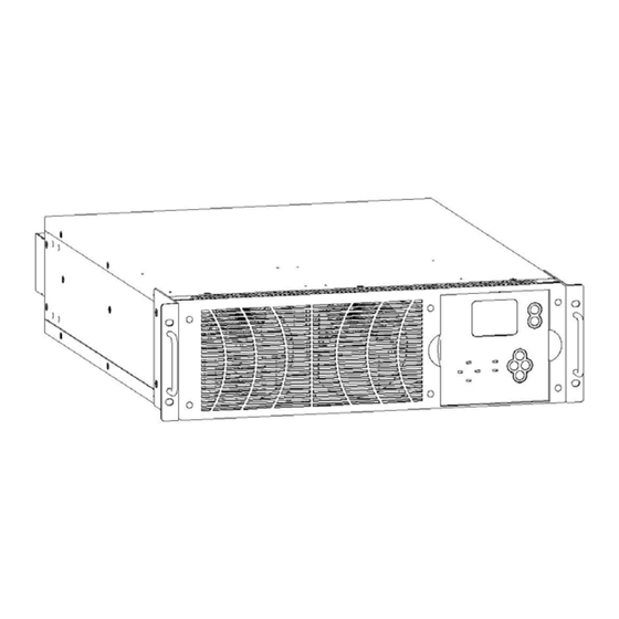
Side View (1) handles (2) fixing screw hole (3) LCD Display (4) Input Terminal (6) Dry contact (7)USB port (8)Intelligent Slot (9)Output Terminal (10)Battery Terminal (11) Input Breaker (12) Parallel Port 1 (13) Parallel Port 2 (14) RS485 (15) EPO 3.3 LCD control panel 开机... -
Page 7: Installation Notes
3.4 Installation notes ◆Please place the UPS in a clean, stable environment, avoid the vibration, dust, humidity, flammable gas and liquid, corrosive objects. To avoid from high room temperature, a system of room extractor fans is recommended to be installed. Optional air filters are available if the UPS operates in a dusty environment. -
Page 8: External Protective Devices
External Protective Devices For safety reasons, it is necessary to install, external circuit breaker at the input A.C. supply and the battery. This chapter provides guidelines for qualified installers that must have the knowledge of local wiring practices for the equipment to be installed. ◆... -
Page 9: Power Cable Connect
CAUTION! Protective earth cable: Connect each cabinet to the main ground system. For Grounding connection, follow the shortest route possible。 WARNING! FAILURE TO FOLLOW ADEQUATE EARTHING PROCEDURES MAY RESULT IN ELECTROMAGNETIC INTERFERENCE OR IN HAZARDS INVOLVING ELECTRIC SHOCK AND FIRE 3.7 Power cable connect Once the equipment has been finally positioned and secured, connect the power cables as described in the following procedure. -
Page 10: Battery Connection
Input connection “3phase 4wires + ground” Input connection “single phase + ground” WARNING! If the load equipment is not ready to accept power on the arrival of the commissioning engineer then ensure that the system output cables are safely isolated at their ends CAUTION! The earthing and neutral bonding arrangement must be in accordance with local and national codes of practice. - Page 11 Note: The BAT+ of the UPS connect poles is connected to the anode of the positive battery, the BAT- is connected to the cathode of the positive battery and the anode of the negative battery, the BAT- is connected to the cathode of the negative battery。 Factory default setting for battery quantity is 16pcs and for battery capacity is 7AH (charger current 1A).
-
Page 12: Ups Multi-Module Installation
3.9 UPS Multi-Module Installation The basic installation procedure of a parallel system comprising of two or more UPS modules is the same as that of single module system. The following sections introduce the installation procedures specified to the parallel system. 3.9.1 Cabinet installation Connect all the UPSes needed to be put into parallel system as below picture. -
Page 13: Parallel Cable Installation
3.9.2 Parallel cable installation Shielded and double insulated control cables available must be interconnected in a ring configuration between UPS modules as shown below. The parallel control board is mounted on each UPS module. The ring configuration ensures high reliability of the control. - 12 -... -
Page 14: Requirement For The Parallel System
3.9.3 Requirement for the parallel system A group of paralleled modules behave as one large UPS system but with the advantage of presenting higher reliability. In order to assure that all modules are equally utilized and comply with relevant wiring rules, please follow the requirements below: 1) All UPS must be of the same rating and be connected to the same bypass source. -
Page 15: Turn On/Off Ups
◆ECO Mode When the UPS is at AC Mode and the requirement to the load is not critical, the UPS can be set at ECO mode in order to increase the efficiency of the power supplied. At ECO mode, the UPS works at Line-interactive mode, so the UPS will transfer to bypass supply. -
Page 16: Inverter Off
CAUTION! Follow these procedures when the input AC Utility Failure, but battery is normal ◆ Turn on the battery switch . The battery will feed the Auxiliary power board . ◆ Trigger the cold start buttons at the position 4 in above drawing. When battery normal, rectifier starts operation, 30s later, inverter starts and operates, INV and output light up. -
Page 17: Parallel Setting
4.2.5 Parallel setting After parallel connections done, start each UPS one by one, and set the paralle ID number, parallel amount and parallel mode respectively. The parallel ID number cannot be the same. Parallel setting in LCD instructions as below: When AC start or battery clode start, at first the main interface will appear, as Fig.1. -
Page 18: Lcd Display Instruction
After setting the parallel amount, press ESC and return to the “setting” menu; then press forward button or backward button to choose “system set” and press ENT to enter it. The system setting menu is as Fig.8; Then ppress ENT to enter “mode” setting as Fig.9. Use the forward button or backward button to set the mode, choose “parallel”... - Page 19 4) An arrow icon will come out on the LCD when pressing the ENT, then, the data info, status info, setting info, command control can be selected by pressing the right or left arrow button, and checking the details by pressing 5)...
- Page 20 Status Status Code/Status Version 0x00 LCD Ver. D000B001 0x000000 DSP Ver. D000B001 Fig18:code info Fig19:version info 7) Select and confirm setting menu , setting information will be displayed on the screen, which includes user setting, system setting, parallel setting, battery setting, revise setting.
- Page 21 Select and confirm parallel menu,then see Fig.29~Fig.30 Setting Setting Parallel Set Parallel Set P-Redund P-Amount NO LBS Fig.29:parallel setting Fig.30:parallel setting Setting battery see Fig. 31~Fig. 34 Setting Setting Setting Battery Set Battery Set Battery Set 1.70 Batt-G Boost 2.30 Batt Num Batt-C Float...
-
Page 22: Working Mode And Transferring
8) Warning message see Fig.41~Fig.46 Warning! Warning! Warning! Interrupt Set no Echo:31 Set Error:31 switch prompt Sure:Ent No:ESC Fig.41 no echo for setting Fig.42 error for setting Fig.43 switch delay Warning! Warning! Warning! Off will cause Off will cause Switch Limited sys.Overload output fail Sure:Ent... -
Page 23: Ups Monitoring
4.4.3 Go to bypass mode due to over temperature The temperature inside UPS may be high if ambient temperature is high or the ventilation is poor, then the UPS will go to Bypass mode, fault indicator will be on (red), the LCD will display that the inner temperature is high, long beeps will come. -
Page 24: Options
4.7 Options Network Management Card with Environmental Monitoring CAUTION! For network management configuration and use, refer to the separate user manual - Network Management Card with Environmental Monitor - shipped with the CARD SNMP card: ◆ Loosen the 2 torque screws (on each side of the card) . ◆... - Page 25 Relay card A 10-pin terminal is supported to offer the signals of Bypass, Utility Failure, Inverter On, Battery Low, UPS fault, UPS Alarm, and UPS Shutdown. The relay communication card contains six dry contact outputs and one dry input. The inputs and outputs are factory programmed according to functions listed in the table Table:Relay Contacts (communication card) Port...
-
Page 26: Appendix 1 Specifications
Appendix 1 Specifications Capacity UPS Module 6KVA/5.4KW, 10KVA/9KW (VA/W) Phase 3 phase 4 wires + Ground or Single phase + Ground Rated Voltage 380/400/415Vac or 220/230/240VAC Voltage Range 208~478Vac or 120-276VAC Frequency Range 40~70Hz Power Factor ≥0.99 Input Max.voltage: +15%(optional +5%、+10%、+25% ) Bypass Voltage Range Min. -
Page 27: Appendix 2 Problems And Solution
Appendix 2 Problems and Solution In case the UPS can not work normally, it might be in wrong installation, wiring or operation. Please check these aspects first. If all these aspects are checked without any problem, please consult with local agent right away and provide below informations. (1)... -
Page 28: Appendix 3 Communication Port Definition
Appendix 3 communication port definition USB communication port Definition of Male port: Pin 1 VCC , Pin 2 D- pin 3 D+ , Pin 4 GND Application use UPSilon2000 Power Management software Available functions of the USB ■ Monitor UPS power status ■... - Page 29 02: (status) Rectifier working Rectifier limit Input normal Input 1:main /0:battery charging P-battery boost charging N-battery boost charging Battery self-testing 00:shutdown;01:soft start; 0:no output;11:output normal Alarm for switch delay Capacity not enough Overload to shutdown Overload to bypass Parallel to bypass Switching times up to limit Master MB switch close...
- Page 30 N loss Battery polarity reversed No battery P-charge fault N-charge fault Battery voltage lower Battery voltage higher pre-alert for battery low Frequency of Input over limit Voltage of Input over limit 0(hold) 0(hold) 04: (Alarm B) Inverter fault Bridge cross of inverter Invert SCR short circuit Invert SCR open circuit bypass SCR short circuit...
Need help?
Do you have a question about the YDC9300-RT Series and is the answer not in the manual?
Questions and answers