
Subscribe to Our Youtube Channel
Related Manuals for KStar STS100


Summary of Contents for KStar STS100
- Page 1 STS100 Static Transfer Switch (STS) Cabinet User Manual Version: V0.0 Date of release: 2023-10-19...
-
Page 3: Table Of Contents
Contents 1. About This Manual ......................4 1.1 Product Definition ....................4 1.2 Applicable Personnel ....................4 1.3 Use of Symbols ......................5 1.4 Safety Precautions ....................6 1.4.1 Electrical Safety ....................6 1.4.2 Lifting and Transportation ................. 7 1.4.3 Installation and Wiring ..................8 1.4.4 Operation and Maintenance ................ - Page 4 4.3 Forklift Transportation ................... 23 4.4 Installation Space Requirements ................25 5. Electrical Connections ....................27 5.1 Safety Precautions ....................27 5.1.1 General ......................27 5.1.2 Five Safety Rules ....................27 5.2 Wiring Overview ..................... 27 5.3 System Wires ......................29 5.4 Preparation before Wiring ..................
- Page 5 8.2.2 Maintenance Work (Semi-annual) ..............48 8.3 Other Maintenance Precautions ................49 9. Appendix ........................50 9.1 Single Cabinet Parameters ..................50 9.2 Tightening Torque ....................51 9.4 Quality Assurance ....................51 9.5 Contact ........................52...
-
Page 6: About This Manual
The content of the manual as well as the pictures, logos and symbols used are all owned by KSTAR. It is not allowed to publicly reproduce all or part of the content without written authorization of KSTAR. -
Page 7: Use Of Symbols
User Manual perform any operations on the product, and should keep a sufficient safe distance from the system to avoid accidents. 1.3 Use of Symbols In order to ensure the user’s personal and property safety when installing this product, or to use this product efficiently and optimally, relevant information is provided in the manual and highlighted with appropriate symbols. -
Page 8: Safety Precautions
User Manual This symbol indicates that this is the protective earth (PE) terminal, which needs to be firmly grounded to ensure the safety of operators. 1.4 Safety Precautions 1.4.1 Electrical Safety High voltage! Risk of electric shock! It is strictly prohibited to touch live parts! •... -
Page 9: Lifting And Transportation
User Manual There is high voltage in the static transfer switch cabinet. Accidental contact may cause fatal electric shock. Therefore, during live measurements, you should: • Take protective measures (such as wearing insulating gloves, etc.). • There must be an accompanying person to ensure personal safety. To prevent unauthorized personnel from misoperation or accidents when approaching the STS100D static transfer switch cabinet, please observe the following precautions: •... -
Page 10: Installation And Wiring
Only qualified electrical engineers may carry out work related to electrical connections. Please abide by the requirements given in the Safety Instructions in this manual. KSTAR shall not be liable for personal injury or property damage caused by ignoring these safety instructions. - Page 11 User Manual • All electrical connections must be made in strict accordance with the wiring diagram. • All electrical connections must be made with the equipment completely de-energized. Only qualified electrical engineers may carry out work related to electrical connections. Please abide by the requirements given in Safety Instructions in this manual.
-
Page 12: Operation And Maintenance
User Manual 1.4.4 Operation and Maintenance If related operations are carried out while the equipment is live, insulation protection must be taken, and at least two workers should be on site at the same time. STS100D static transfer switch cabinet is outdoor equipment and is usually located in a field environment away from the urban area, and the corresponding field rescue facilities should be prepared according to the needs, so that they can be carried out when needed. -
Page 13: Product Scrapping
User Manual In order to avoid unnecessary casualties and equipment damage, the product must be operated strictly according to the description in this manual. If the operation is improper, it may cause an arc hazard, and may even cause fire, explosion and other risks. The company will not be liable for any accidents such as arcs, fires, explosions and other accidents caused by failure to operate in accordance with the signs or product manual. -
Page 14: Product Description
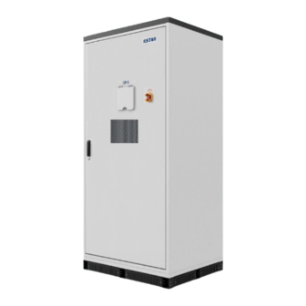
2. Product Description 2.1 Introduction This STS100D static transfer switch cabinet produced by KSTAR is mainly used in industrial and commercial scenarios. It consists of outer cabinet, transformer module, touch screen and electrical components. It has a protection grade of IP54 and can be installed outdoors. -
Page 15: Mechanical Parameters
User Manual Figure 2-2 Front view of STS100D static transfer switch cabinet Name Nameplate Door lock switch EMS display 2.2.2 Mechanical Parameters The appearance dimensions of the STS100DD static transfer switch cabinet are shown in Figure 2-3 below. - Page 16 User Manual Figure 2-3 Dimensional drawing of STS100DD static transfer switch cabinet *The above picture takes STS100DD static transfer switch cabinet as an example. It is for reference only. Please refer to the actual product received!
-
Page 17: System Design
User Manual 2.3 System Design 2.3.1 System Equipment Layout The overall location distribution of electrical components in the STS100DD static transfer switch cabinet system is shown in Figure 2-4. Figure 2-4 Overview of the location of electrical components Name Abbreviation M02 board U01 board X02 board... - Page 18 User Manual Name Abbreviation Auxiliary circuit board 2 STS thyristor module SPD-KS Lightning protection circuit breaker GRID Grid circuit breaker SPD-AC Lightning arrestor LOAD Load breaker BYPASS Maintenance switch Air conditioning switch 1, air Air Conditioner 1/2 conditioning switch 2 *The above picture takes STS100DD static transfer switch cabinet as an example.
-
Page 19: Function Introduction
User Manual Name Abbreviation N line copper bar Load terminal LOAD U, LOAD V, LOAD W Ground copper bar Note: The internal wiring has been completed before leaving the factory. Please connect the external input wiring in order according to the label. 2.3.2 Function Introduction Figure 2-6 STS100D static transfer switch cabinet wiring schematic diagram The wiring schematic diagram of the STS100D static transfer switch cabinet is shown in Figure 3-5. - Page 20 User Manual The STS100D static transfer switch cabinet is equipped with circuit breaker switches on the grid side and the load side. The grid bypass maintenance switch is used to facilitate power supply from the grid side to the load side during maintenance. The oil engine bypass maintenance switch is used to facilitate power supply from the oil engine side to the load side during maintenance.
-
Page 21: Delivery And Storage
User Manual 3. Delivery and Storage 3.1 Scope of Supply When shipped, the shipping list of the STS100D static transfer switch cabinet is as follows: Static Transfer Switch Cabinet User Manual Certificate Warranty Card Test Report Spare Screws *The above pictures are for reference only. Please refer to the actual product received! Figure 3-1 Illustration of delivery list of static transfer switch cabinet Table 3-1 Scope of supply Name... -
Page 22: Storage
User Manual After receiving the equipment, first check the completeness and integrity of the transportation. At a minimum, the following items should be carefully checked: • Check whether all delivered components are complete against the “scope of supply”. • Confirm that the STS100D static transfer switch cabinet and internal equipment models received are consistent with the model you ordered previously. -
Page 23: Mechanical Installation
User Manual 4. Mechanical Installation During the entire process of mechanical installation, the relevant standards and requirements of the project location must be strictly followed. 4.1 Inspection before Installation 4.1.1 Checking the Deliverables Check whether the delivery is complete against the accompanying packing list. 4.1.2 Checking Equipment If you find problems or have questions, please contact the transporter or our company in time. - Page 24 User Manual Figure 4-1 Front view of reference foundation Figure 4-2 Top view of reference foundation Unreasonable foundation construction plans will cause great difficulties or troubles in the placement of equipment, opening and closing doors, and later operation. Therefore, the installation foundation of equipment must be designed and constructed in advance according to certain standards to meet the requirements of mechanical support, cable routing, and subsequent maintenance and inspection.
-
Page 25: Forklift Transportation
User Manual • The foundation shall be made according to the reference foundation drawing provided by KSTAR, or the foundation drawing confirmed by our company. The upper surface tolerance of the foundation shall be ±5mm. • The foundation must be sufficient to provide effective load-bearing support for STS100D. - Page 26 User Manual If forklift transportation is used, the following requirements should be met: • The door of STS100D is locked tightly. • The length of the pins should be at least 1100mm. The prongs should be plugged into the fork jack in the bottom of the workstation (see Figure 4-2 below for the location of the fork jack).
-
Page 27: Installation Space Requirements
User Manual The sockets of the cabinet are exposed before delivery. It is recommended that the sockets be sealed with accessory sealing plates after on-site installation. 4.4 Installation Space Requirements In order to ensure better heat dissipation and maintenance of the equipment, it is recommended to reserve sufficient space around the cabinet installation location. - Page 28 User Manual Figure 4-5 Dimensional drawing of equipment base Note: The base is fixed with 8 screws (M12*50). The specific installation position and direction are determined by the customer. *The above pictures are for reference only. Please refer to the actual item received!
-
Page 29: Electrical Connections
User Manual 5. Electrical Connections 5.1 Safety Precautions 5.1.1 General High voltage! Risk of electric shock! It is strictly prohibited to touch live parts! • Before installation, please make sure that the AC and DC sides are not powered. • Do not place the static transfer switch cabinet on a flammable surface. - Page 30 User Manual Figure 5-1 STS100D static transfer switch cabinet wiring diagram The schematic diagram of the external wiring principle is shown in 5-1. It only describes the wiring principle and the picture is for reference only. Note: The miniature circuit breakers for the fuse, auxiliary power and air conditioning switch are equipped with labels.
-
Page 31: System Wires
5A. The connecting wires on the same side should be of the same specifications and types. KSTAR has provided the reference requirements for the sizes of various types of cables, and the cable lengths are determined according to the on-site installation environment. -
Page 32: Preparing Cables
User Manual Socket Multimeter Wire stripper Phillips screwdriver (M6/M8/M12/M16) Insulated adjustable Heat shrink tubing wrench Figure 5-2 Schematic diagram of installation tools 5.4.2 Preparing Cables Before making electrical connections, check and ensure the integrity and insulation of the cables used. If there are damaged cables, replace in time. Poor insulation or damaged cables can be dangerous. -
Page 33: Copper Wire Connection
User Manual Step 1: Peel off the insulation at the end of the cable. The length of the insulation peeled off should be the depth of the wiring copper nose crimping hole plus 5mm. Step 2: Crimp wiring copper nose. First put the exposed copper core of the stripped wire into the crimping hole of the wiring copper nose. -
Page 34: Wiring Guidelines And Precautions
User Manual Name Bolt Spring washer Flat washer Note: The cables connecting the STS and external equipment enter the interior from the cable entrance at the bottom of the cabinet, and the foundation is designed with reserved cable troughs. 5.4.5 Wiring Guidelines and Precautions Before wiring, check the phase sequence of all input cables to ensure that the phase •... - Page 35 User Manual Step 3: Crimp with OL50-10 terminal; refer to 5.4.3 Making Terminals. Step 4: Insert the PV/load cable from the bottom of the STS cabinet into the cable entry hole and into the wiring area inside the STS cabinet. Step 5: Make sure the PV/load connection sequence is correct.
- Page 36 User Manual Figure 5-4 Air conditioner wiring diagram ⑤ Communication wiring The communication connection terminal is at the lower left of the STS, and the communication port is shown in Figure 5-5 below. Step 1: According to the communication label, lead the (CAN+485) communication and TCP communication cables from the STS cabinet into the cable entry hole and into the internal wiring area of the STS cabinet.
- Page 37 User Manual (CAN+485) Communication: For communication between PCS and STS, the communication cable is already equipped at the factory, but the user needs to connect it with a flat-blade screwdriver in the order of the wire markings. The parallel port labels from left to right are: 1, 2, 3, 4, 5, 6, 7, 8. TCP communication: The communication between BC100DE and STS is TCP communication.
-
Page 38: Ground Connection
User Manual Figure 5-7 DC power wiring diagram 5.5 Ground Connection 5.5.1 Introduction Ground connections must comply with the grounding standards and regulations of the country where the project is located. During grounding, please note that the ground connection between the equipment and the ground electrode must be reliably fixed. -
Page 39: Internal Equipment Grounding
During the grounding connection process, if you have any questions, please contact relevant staff in time. Failure to follow installation specifications, or unauthorized installation or modification may result in safety accidents or equipment damage. KSTAR does not assume any responsibility for any losses caused by this. - Page 40 User Manual Interface name Pin description Remarks number number definition Negative pole of power supply Power supply input Power supply range is Ground pin interface 9-20VDC Positive pole of power supply 10/100M Ethernet Ethernet port 1 port (reserved) 10/100M Ethernet Ethernet port 2 port AGND...
- Page 41 User Manual Channel-2 RS485 signal A Isolated RS485 RS485 interface 2 interface 2, reserved Channel-2 RS485 signal B Channel-3 RS485 signal A Isolated RS485 RS485 interface 3 interface 3, reserved Channel-3 RS485 signal B Channel-4 RS485 signal A Isolated RS485 JP11 RS485 interface 4 interface 4, reserved...
-
Page 42: Cabling And Waterproofing
User Manual Channel-4 relay output common COM4 terminal Channel-4 relay output normally open terminal Channel-3 relay output common COM3 terminal Channel 1-4 relay Channel-3 relay output normally switching output, open terminal Digital output Normally open output, interface 1 Channel-2 relay output common COM2 Capacity is 2A terminal... -
Page 43: Ending Electrical Connections
User Manual 5.8 Ending Electrical Connections After the electrical connections are completed, the connections of all cables need to be checked. Make sure all connections are correct and tight. After all electrical connections are made, the wiring should be thoroughly and carefully inspected. •... -
Page 44: Power On/Off Operations
User Manual 6. Power on/off Operations Only after confirmation by professionals and permission from the local power department can the STS static transfer switch cabinet is put into operation. For STS static transfer switch cabinets that have a long downtime, the equipment must be comprehensively and carefully inspected before powering on to ensure that all indicators meet the requirements. -
Page 45: Power-Off Operation
User Manual Step 2: Close the AC auxiliary power switch, and then check the alarm interface on the screen to see if there are any faults; Step 3: Close the grid circuit breaker switch and check whether the grid voltage on the EMS screen is normal;... -
Page 46: Troubleshooting
User Manual 7. Troubleshooting Table 7-1 Common Fault Types and Solution Type Solution Parallel communication Check whether the parallel communication cable connection is normal failure No module fault Check whether the inverter module is properly connected to the STS cabinet EPO fault Manually shut down Check whether the communication cable between the inverter and EMS is... - Page 47 User Manual Busbar voltage failure of slave Check whether PCS5 is running normally Communication failure of Shut down the machine and check whether the inverter communication slave 5 cable is normal Grid UV voltage too high fault Shut down the machine and check the voltage at the grid connection point Grid VW voltage too high Shut down the machine and check the voltage at the grid connection point fault...
-
Page 48: Routine Maintenance
8.1 Instructions before Maintenance • Please do not open the outdoor cabinet for maintenance in rainy, humid or windy weather. If it cannot be avoided, KSTAR will not be responsible for any losses caused by disconnecting the AC and DC side switches. •... - Page 49 User Manual Item Method blocked. Check the following items. If they do not meet the requirements, correct immediately: • Check whether there are foreign objects, dust, dirt and condensation inside the STS cabinet, which need to be cleaned. Cabinet • Check whether the STS cabinet and internal equipment are interior damaged or deformed.
-
Page 50: Maintenance Work (Semi-Annual)
User Manual Item Method Warning Check whether warning signs and labels are clearly visible and not signs defaced. Replace if necessary. • Check the grounding of cable shielding layer is grounded. Check Grounding of whether the cable shielding layer and the insulating sleeve are in cable good contact. -
Page 51: Other Maintenance Precautions
If you have any questions about the operation and maintenance of the equipment, please contact the KSTAR Customer Service Center. Unauthorized operation is strictly prohibited. When performing routine maintenance, inspection and other work on the internal equipment of the static transfer switch cabinet, once any non-compliance is found, please correct it immediately. -
Page 52: Appendix
User Manual 9. Appendix 9.1 Single Cabinet Parameters (Authentication parameters are consistent, table) Model STS100D Parameters Rated grid voltage 400 V Rated grid current 144A Grid voltage range 340~440V Rated power 100KVA Maximum current (charge + load) 288A Rated grid frequency 50Hz/60 Hz Grid switch switching time ≤20ms... -
Page 53: Tightening Torque
To reduce the stress on the wiring copper nose, the cables should be fixed at appropriate position. 9.4 Quality Assurance For products that fail during the warranty period, Shenzhen Kstar New Energy Co., Ltd. (the “Company”) will repair or replace new products free of charge. During the warranty period, the Company will ask the customer to show the invoice and date of purchase of the product. -
Page 54: Contact
Fault code/name • Brief description of the fault Shenzhen Kstar New Energy Co., Ltd. Address: Kstar Industrial Park, No. 7 Road, West Section, High-tech Park, Guangming District, Shenzhen Postal code: 518106 After-sales service hotline: 400-700-9662 Headquarters Tel: 0755 - 2138 9008 Website: www.kstar.com...
Need help?
Do you have a question about the STS100 and is the answer not in the manual?
Questions and answers