Table of Contents
Advertisement
PZ 99E User Manual
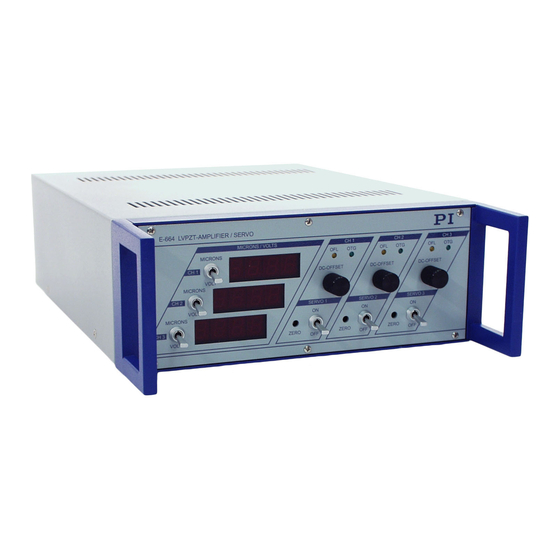
E-664
LVPZT Position Servo Controller
Release: 1.0.4
Date: 2003-10-15
This document describes the
following product(s):
E-664.S3
LVPZT Servo Controller
© Physik Instrumente (PI) GmbH & Co. KG
Auf der Römerstr. 1 ⋅ 76228 Karlsruhe, Germany
Tel. +49 721 4846-0 ⋅ Fax: +49 721 4846-299
s ⋅ www.pi.ws
info@pi.w
Advertisement
Table of Contents

Related Manuals for PI E-664


Summary of Contents for PI E-664
- Page 1 Date: 2003-10-15 This document describes the following product(s): E-664.S3 LVPZT Servo Controller © Physik Instrumente (PI) GmbH & Co. KG Auf der Römerstr. 1 ⋅ 76228 Karlsruhe, Germany Tel. +49 721 4846-0 ⋅ Fax: +49 721 4846-299 s ⋅ www.pi.ws info@pi.w...
-
Page 2: Table Of Contents
Electrical Capacitance of Different PI PZTs......15 Front Panel Elements ............. 16 Rear Panel Elements ............17 8.1. Connectors................. 18 NanoCube Handling ............19 © Copyright 2005 by Physik Instrumente (PI) GmbH & Co. KG Release: 1.0.4 File:E-664_User_PZ99E104.doc, 260608 Bytes Release 1.0.4 www.pi.ws Page 2... -
Page 3: Manufacturer Declarations
Buyer. PI does not warrant the Buyer's circuitry or malfunctions of PI products that result from the Buyer's circuitry. In addition, PI does not warrant any damage that occurs as a result of the Buyer's circuit or any defects that result from Buyer-supplied products. -
Page 4: Warnings And Safety Instructions
CAUTION: Calibration Information If you inform PI about your application, your E-664 will be fully calibrated before being shipped. It is usually not necessary for you to do anything more than adjust the zero point before operating the system. -
Page 5: Introduction
This manual describes the functionality and the use of E-664 LVPZT Amplifier / Position Servo Controller The E-664 is a bench-top device to operate up to three low-voltage piezoelectric translators (LVPZTs) in open-loop and closed-loop (position controlled) mode. The E-664 can be used with LVPZTs equipped with strain gauge displacement sensors. -
Page 6: Quick Start
User Manual PZ 99E Quick Start The E-664 PZT Controller was calibrated with the PZT translators before shipment. During the calibration process, the expansion of the PZT is compared with an external standard scale. Individual characteristics of the amplifier and servo- controller are compensated. -
Page 7: Troubleshooting
E-664 LVPZT Position Servo Controller User Manual PZ 99E 2.2. Troubleshooting No Operation—Display is dark after switching on Check supply voltage and fuse. Display in MICRON mode shows no change Make sure NanoCube is connected and cable is not defective. -
Page 8: Closed-Loop (Servo On) Mode
E-664 LVPZT Position Servo Controller User Manual PZ 99E 3.2. Closed-Loop (Servo ON) Mode 3.2.1. Manual Operation Displacement of the PZTs can be set by a 10-turn DC-Offset potentiometer in the range of zero to nominal displacement. For manual operation CONTROL IN should clamped at 0 V. -
Page 9: Block Diagram
E-664 LVPZT Position Servo Controller User Manual PZ 99E Block Diagram Servo-control functions are implemented on an E-802 submodule. The respective User Manual provides detailed information. Fig. 2 E-664 block diagram Note: The potentiometer labelling P1-P5 shown above is that used on the E-802.55-type plug-in submodules, on which these functions are implemented. -
Page 10: Adjustment And Calibration Procedures
User Manual PZ 99E Adjustment and Calibration Procedures CAUTION: If you inform PI about your application, your E-664 will be fully calibrated before being shipped. It is usually not necessary for you to do anything more than adjust the zero point before operating the system. - Page 11 LVPZT should not exceed +100 V in order to maintain a long lifetime. The E-664 amplifiers have an output range from -20 V to +120 V. In this case, the zero position PZT voltage can be set within the range from -10 V to +10 V.
- Page 12 E-664 LVPZT Position Servo Controller User Manual PZ 99E Mount an external gauge to measure the PZT displacement. (with PZT power amplifier powered down, the external gauge should read 0; if it does not, note the offset and subtract it from subsequent readings) Set the switch on the front panel to Servo OFF.
-
Page 13: Main Board Calibration Elements
E-664 LVPZT Position Servo Controller User Manual PZ 99E 5.2. Main Board Calibration Elements R152- R154 Sensor Gain R187-R189 Sensor Tolerance Fig. 3 Adjustment element and submodule locations Release 1.0.4 www.pi.ws Page 13... -
Page 14: Dynamic Calibration
E-664 LVPZT Position Servo Controller User Manual PZ 99E 5.3. Dynamic Calibration Dynamic performance of the PZT system is determined by the maximum output current of the amplifier and by the mechanical properties of the PZT mechanics, like moving mass, damping and resonant frequencies. Dynamic calibration optimizes step response and suppresses resonance, overshoot, and oscillation. -
Page 15: Frequency Response
E-664 LVPZT Position Servo Controller User Manual PZ 99E 6.1. Frequency Response E-664 open-loop frequency response with various PZT loads. Capacitance values are in µF. Fig. 4. Frequency response with a selection of PI PZTs Electrical Capacitance of Different PI PZTs 6.2. -
Page 16: Front Panel Elements
E-664 LVPZT Position Servo Controller User Manual PZ 99E Front Panel Elements perating and display elements Fig. 5. Front panel o VOLTS/MICRONS Toggle switch for LED Display VOLTS: Display showing current PZT output MICRONS: Display showing current sensor reading Overflow LED... -
Page 17: Rear Panel Elements
E-664 LVPZT Position Servo Controller User Manual PZ 99E Rear Panel Elements Line Switch Power On/Off (opens completely) Voltage Selector Two default ranges (220-240 V or 110-120 V). Selected value is visible in window (see figures). Pry out and re-orient fuse carrier to change range selection. -
Page 18: Connectors
E-664 LVPZT Position Servo Controller User Manual PZ 99E 8.1. Connectors 8.1.1. Piezo Stage Connector (Backpanel) Type: Sub-D 25 pin female Fig. 7. Caution: Voltage up to 130 V on pins 11, 12 and 13 8.1.2. I/O Connector (back panel) Fig. -
Page 19: Nanocube Handling
E-664 LVPZT Position Servo Controller User Manual PZ 99E NanoCube Handling Fig. 9 P-611.3SF and P-611.3OF versions Fig. 10. P-611.3S and P-611.3O versions Release 1.0.4 www.pi.ws Page 19...
Need help?
Do you have a question about the E-664 and is the answer not in the manual?
Questions and answers