Advertisement
Quick Links
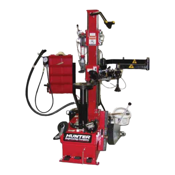
INSTALLATION INSTRUCTIONS FOR TCA28 TIRE CHANGER
NOTE:
Read and become familiar with these instructions before starting installation.
WARNING: Read and follow all caution and warning labels affixed to your
Placement
The TCA28 should be placed in a dry area which is not subjected to water spray.
The TCA28 is best positioned with the back of the unit against a wall. Clearance for the operator at the front and
left of the tire changer should be at least 3 feet. There must also be ample clearance to the right of the tire
changer to allow the bead breaking arm to fully extend. Workspace and operating dimensions are shown below.
The electrical power cord and air hose should be positioned so that it cannot be walked on, driven over, or tripped
over.
This procedure should be performed only by an authorized factory
representative.
equipment and tools. Misuse of this equipment can cause personal
injury and shorten the life of the tire changer.
1 of 28
Form 6215-T, 11-10b
Advertisement

Related Manuals for Hunter TCA28


Summary of Contents for Hunter TCA28
- Page 1 The TCA28 should be placed in a dry area which is not subjected to water spray. The TCA28 is best positioned with the back of the unit against a wall. Clearance for the operator at the front and left of the tire changer should be at least 3 feet. There must also be ample clearance to the right of the tire changer to allow the bead breaking arm to fully extend.
- Page 2 The customer must furnish 230VAC, 60 HZ, service for maximum 12 AMP draw, single-phase power for the TCA28. Power source requirements of TCA28 are located on the Hunter serial number plate. Changes to the AC power cord, plug and/or power source must be performed by a certified electrician.
- Page 3 4. Remove and set aside accessory boxes (Fig. 2). Fig.2 5. Remove the bolts securing the tire changer to the pallet. 6. Remove tire changer from pallet. 7. Position the tire changer on the floor. Install Column to Base CAUTION: The column is heavy and may require two persons to lift safely. NOTE: The hardware to help secure the column to the base is comprised of the following:...
- Page 4 1. Remove the fixation plate of the column (Fig. 3). Make sure that the column is still sitting balanced on the two wooden supports before removing this plate. Fig. 3 2. Mount the two screws (M8 x 80, all threaded) with the washers and the nuts in the outer holes (Fig. 4). NOTE: These (all threaded screws) are only used for assisting in the mounting of the column.
- Page 5 5. Remove the two (all threaded screws), nuts and washers that were used only to mount the column. (Fig. 7) Fig. 7 6. Open the left side cover and finish securing the column with the rest of the attachment hardware. NOTE: The short air line indicated in Fig.
- Page 6 Install Command Unit Arm 1. While lifting the command unit arm into position, route the air lines into the column (Fig. 9) NOTE: If command unit arm is already installed, proceed to "Install Side Shovel", page 7. Fig. 9 2. Position the command unit arm in the upper bracket (Fig. 10). Secure upper and lower guide screws in the guide screw channels (Fig.
- Page 7 3. Secure the command unit arm at the pivot point (Fig. 12). Do not over-tighten the screw / nut. Check that the arm swings freely. Fig. 12 Install Side Shovel 1. Remove the bolt securing the side shovel pivot pin (Fig. 13) and lift the pin (Fig. 14). Fig.
- Page 8 2. Position the side shovel at the pivot point but do not insert the pivot pin. Insert the side shovel retraction shaft in the side shovel arm and hand tighten the nut (Fig. 15). Fig. 15 3. Secure the side shovel return spring to the hook on the "body" side of the side shovel (Fig. 16), and to the shovel arm (Fig.
- Page 9 4. Re-install the side shovel pivot pin and secure the bolt (Fig. 18). Fig. 18 5. Move the side shovel completely out so the side shovel retraction shaft and bolt are easily accessible (Fig. 19). Return side shovel to the "in" position (Fig. 20). Fig.
- Page 10 7. Install the plastic side shovel protector (Fig. 22). Fig. 22 Install Bead Press Arm 1. Remove the bolt from the bead press arm pivot point (Fig. 23). Fig. 23...
- Page 11 2. Position the bead press arm at the pivot point. Insert the bead press arm bolt through the bracket and bead press arm and install the washer and nut (Fig. 24). Fig. 24 3. Fully seat the bead press arm bolt and secure with hex head socket cap screw (Fig. 25). Do not over-tighten the bolt / nut.
- Page 12 Install Air Tank - Without Wheel Lift NOTE: If installing a wheel lift, refer to "Install Air Tank and Wheel Lift - (for models with wheel lift)", page 14. 1. Secure the air tank to the rear of the tire changer with the bolts, washers and nuts provided (Fig. 27). Larger bolt / washer / nut is on the top of the air tank bracket (Fig.
- Page 13 3. Route the orange air line (Fig. 31) through the upper rear port without grommet (Fig. 32). Fig. 31 Fig. 32 4. Position the side panel and secure with hardware previously removed (Fig. 33). Fig. 33 5. Air tank installation is now complete. Proceed to "Install Side Storage Shelf" on page 21.
- Page 14 Install Air Tank and Wheel Lift - (for models with wheel lift) NOTE: This section documents the entire wheel lift installation procedure. If not installing a wheel lift, refer to "Install Air Tank - Without Wheel Lift", page 12. NOTE: Refer to this illustration when routing air lines (Fig.
- Page 15 2. Remove the rear air line manifold cover (Fig. 36 - Fig. 37). Fig. 36 Fig. 37 3. Position the wheel lift valve and pedal assembly near the side of the tire changer (Fig. 38). Route the wheel lift pedal air lines into the tire changer base (Fig. 39). Continue routing the air lines above the motor bracket (Fig.
- Page 16 4. Route the two "wheel lift cylinder" air lines out of the lower rear port with grommet (Fig. 42 - Fig. 43). Fig. 42 Fig. 43 5. Route the "manifold" air line out of the lower rear central port. Remove the existing plug and connect the "manifold"...
- Page 17 7. Remove the inflator pedal protector bracket from the side panel (Fig. 48). Fig. 48 8. Remove the inflator valve from the side panel. Remove the foot pedal. (Fig. 49) Fig. 49 9. Install the pedal extension. (Fig. 50) Fig. 50...
- Page 18 10. Re-install the inflator valve to the side panel. Re-install the foot pedal. (Fig. 51) Fig. 51 11. Route the orange air line (Fig. 52) through the upper rear port without grommet (Fig. 53). Fig. 52 Fig. 53 12. Position the wheel lift bracket on the tire changer base. Hand tighten the two bolts, washers and nuts as shown below.
- Page 19 13. Secure the flat bracket to the air tank. (Fig. 55) Fig. 55 14. Position the air tank on the wheel lift bracket (Fig. 56). Secure the air tank to the wheel lift bracket with two bolts, washers and nuts as shown below. Secure all bolts, washers and nuts on the wheel lift bracket and air tank bracket.
- Page 20 16. Locate and connect the "wheel lift cylinder" black air lines to the top (Fig. 59) and bottom of wheel lift cylinder (Fig. 60). Refer to the illustration on page 14. Fig. 59 Fig. 60 17. Position the wheel lift assembly on the side of the tire changer and secure to wheel lift bracket with 4 bolts provided (Fig.
- Page 21 18. Locate and connect the black air line to the blast inflation hose valve (Fig. 63). Locate and connect the blue air line to the fitting on the side of the tank (Fig. 64). Fig. 63 Fig. 64 19. Replace the rear air line manifold cover. 20.
- Page 22 2. Loosen but do not remove the top screws on the side storage shelf bracket (Fig. 67). Remove the bottom screws on the side storage shelf bracket (Fig. 68). Fig. 67 Fig. 68 3. Position the side storage shelf on the bracket (Fig. 69). Fig.
- Page 23 4. Tighten the top screws (Fig. 70). Install and tighten the bottom screws (Fig. 71). Fig. 70 Fig. 71 5. Position the bead blast nozzle holder onto the top of the inflator gauge assembly. Secure the inflator gauge / bead blast nozzle holder assembly to the side of the storage shelf using two screws as shown (Fig. 72). TOP SCREW BEAD BLAST NOZZLE...
- Page 24 Install Mirror 1. Locate and remove the two bolts on the side of the lower carriage (Fig. 74). Position mirror and secure with screws previously removed (Fig. 75). Fig. 74 Fig. 75 Install Paste Bucket Holder 1. Loosen the two bolts on the paste bucket bracket. Slide paste bucket holder onto bracket and secure bolts. 2.
- Page 25 Final Assembly Procedures 1. Connect L6-20 plug to electric cable and connect to electrical supply. NOTE: Connect green/yellow striped wire to ground (bent blade), brown and blue wires connect to X and Y (Fig. 77). Fig. 77 2. Using the supplied wire tie, secure the hose retainer to the base of the tire changer (Fig. 78). Secure such that the hose retainer does not contact the bottom of the column, or curl under the inflation tank as the column moves vertically.
- Page 26 3. Connect air chuck to inflator hose (Fig. 79). CAUTION: Excessive amounts of Teflon thread sealant can cause pneumatic blockage. Use Teflon thread sealant sparingly. Fig. 79 4. Connect main air supply to regulator (Fig. 80). CAUTION: Excessive amounts of Teflon thread sealant can cause pneumatic blockage. Use Teflon thread sealant sparingly.
- Page 27 10. Fill oiler with Hunter Lubri-Oil supplied or ONLY mineral oil. NEVER USE air tool oil or ATF. 11. Assemble the bead depressor traction bar by securing the plastic wedge with the long screw at the end of the traction bar (Fig. 81).
- Page 28 3. Install a 5/16 inch anchor bolt into each foot securing the tire changer to the floor. Modification Instructions for Nitrogen Tire Fill The TCA28 can be easily modified to allow the use of nitrogen for the bead blast nozzle and tire fill hose. 1. Disconnect the air supply from the tire changer.
Need help?
Do you have a question about the TCA28 and is the answer not in the manual?
Questions and answers