Extron electronics MTP 1500RL 15HD RS Series Setup Manual
Hide thumbs
Also See for MTP 1500RL 15HD RS Series:
- User manual (23 pages) ,
- Setup manual (2 pages) ,
- User manual (17 pages)
Advertisement
Quick Links
Setup Guide — MTP 1500RL 15HD RS Series
SELECT
INPUT
BUFFERED OUTPUT
POWER
12V
1.0A MAX
MTP
MTP
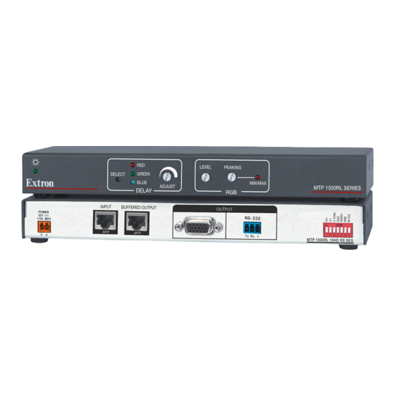
This guide provides basic instructions for an experienced installer to set up and operate any of
the Extron
MTP 1500RL 15HD RS series of extended mini twisted pair receivers; the
®
MTP 1500RL 15HD RS and the MTP 1500RL 15HD RS SEQ (model shown above). For full
details, refer to the MTP 1500RL 15HD RS Series User's Manual, available at www.extron.com.
Installation
Step 1 — Mounting
Turn off or disconnect all equipment power sources
and mount the MTP 1500RL 15HD receiver as required.
Step 2 — Connect input
Connect the RJ-45 cable from an MTP transmitter
to the Input port on the MTP 1500RL 15HD receiver.
Terminate the cable as shown on the right, using the
same standard (A or B) at both ends.
Step 3 — Connect outputs
Attach the applicable output cables (video, RS-232, and buffered output).
a. High resolution video output — Connect a suitable display device to the 15-pin HD
connector (RGB).
b. RS-232 connector — Connect an RS-232 compatible device into the 3-pole captive screw
connector (wired as below) for bidirectional or unidirectional communication up to
1,000 feet (maximum).
Connected RS-232
Device Pins
Receive
Transmit
Ground
c. Buffered output — Connect up to 8 daisy-chained MTP receivers to this RJ-45 connector.
Step 4 — Receiver DIP switches
•
H sync (H+) and V sync (V+) switches — Set these switches up (On)
for positive sync or down for negative sync.
•
Composite Sync, (SOG), and Video switches — Set these switches as
shown in the table at right to output the indicated format.
•
End Unit switch — Set this switch up if either of the
following is true:
a. The receiver being configured is the only
receiver connected to the transmitter.
b. The receiver being configured is the last
receiver in a daisy-chained system.
•
BI-232 switch — Set this up (On) for bidirectional
or down for unidirectional communication.
RED
LEVEL
PEAKING
GREEN
BLUE
ADJUST
DELAY
RGB
OUTPUT
MTP
MTP
Gnd
(Continued on reverse side)
MIN/MAX
MTP 1500RL SERIES
RS-232
ON
MTP 1500RL 15HD RS SEQ
Tx
Rx
1 2 3 4 5 6 7 8
Insert
TP Wires
MTP Reciever
Pins
Tx
Rx
Pins:
T568A
Pin
Wire color
1
White-green
2
Green
3
White-orange
4
Blue
5
White-blue
6
Orange
7
White-brown
8
Brown
NOTE
If you are using Enhanced
Skew-Free
™
A/V cable, use the
TIA/EIA T568A standard only.
ON
Output
C Sync SOG Video
Format
Format
RGBHV
RGBS
RGsB
Component*
S-video*
Composite*
* Input video format must match.
T568B
Wire color
White-orange
Orange
White-green
Blue
White-blue
Green
White-brown
Brown
Advertisement

Related Manuals for Extron electronics MTP 1500RL 15HD RS Series


Summary of Contents for Extron electronics MTP 1500RL 15HD RS Series
- Page 1 MTP 1500RL 15HD RS series of extended mini twisted pair receivers; the ® MTP 1500RL 15HD RS and the MTP 1500RL 15HD RS SEQ (model shown above). For full details, refer to the MTP 1500RL 15HD RS Series User’s Manual, available at www.extron.com. Installation Pins:...
- Page 2 Setup Guide — MTP 1500RL 15HD RS Series, cont’d Step 5 — Power Smooth Ridges Plug the included external 12 VDC power supply into the Captive Screw 2-pole captive screw connector. Wire the connector as shown. Connector Tie Wrap Step 6 — Peaking and Level 3"...
Need help?
Do you have a question about the MTP 1500RL 15HD RS Series and is the answer not in the manual?
Questions and answers