
Related Manuals for Waters 2707


Summary of Contents for Waters 2707
- Page 1 Waters 2707 Autosampler Operator’s Guide 71500168202 / Revision A Copyright © Waters Corporation 2008 All rights reserved...
- Page 2 Corporation assumes no responsibility for any errors that may appear in this document. This document is believed to be complete and accurate at the time of publication. In no event shall Waters Corporation be liable for incidental or consequential damages in connection with, or arising from, its use.
- Page 3 Customer comments Waters’ Technical Communications department invites you to tell us of any errors you encounter in this document or to suggest ideas for otherwise improving it. Please help us better understand what you expect from our documentation so that we can continuously improve its accuracy and usability.
- Page 4 Contacting Waters ® Contact Waters with enhancement requests or technical questions regarding the use, transportation, removal, or disposal of any Waters product. You can reach us via the Internet, telephone, or conventional mail. Waters contact information Contacting medium Information Internet The Waters Web site includes phone numbers for Waters locations worldwide.
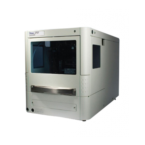
- Page 5 Intended use Waters designed the 2707 Autosampler as a sample handler with a reliable, precise fluid path versatile enough for use in varied methods and applications. The optional heating/cooling module accommodates a wide range of samples, from heat labile biological samples to viscous polymer samples.
-
Page 7: Table Of Contents
Table of Contents 1 Understanding Operating Principles ..........1-1 Describing the autosampler ................1-2 Listing component parts.................. 1-3 Identifying options ................... 1-5 Exploring injection principles ............... 1-6 Defining pressure-assisted sample aspiration ..........1-6 Understanding syringe and buffer tubing ............1-7 Full loop injections................... - Page 8 Installing the prep kit ..................2-14 Installing the biocompatibility kit .............. 2-14 3 Maintaining the Autosampler ............. 3-1 Outlining maintenance basics ............... 3-2 Contacting Waters Technical Service ............3-2 Heeding maintenance considerations ............3-3 Safety and handling..................3-3 Proper operating procedures ................3-4 Cleaning the autosampler ................
- Page 9 Task-specific hazard warnings................ A-2 Warnings that apply to particular instruments, instrument components, and sample types A-3 Caution symbol ....................A-5 Warnings that apply to all Waters instruments ......... A-5 Electrical and handling symbols ..............A-13 Electrical symbols ..................A-13 Handling symbols ..................A-14...
- Page 10 B Materials of Construction and Compliant Solvents ..... B-1 Preventing contamination ................B-2 Naming solvents for mobile phase preparation ........B-2 C Specifications ..................C-1 Outlining general specifications ..............C-2 Outlining prep version specifications ............C-6 Table of Contents...
-
Page 11: Understanding Operating Principles
Understanding Operating Principles Contents Topic Page Describing the autosampler Identifying options Exploring injection principles Using well plates and vial trays 1-24... -
Page 12: Describing The Autosampler
Describing the autosampler The Waters 2707 Autosampler is a comprehensive, high-throughput instrument that offers the following features: • Service-friendly design that requires little bench space • High-resolution syringe control for high-precision injections • Interchangeable fixed-volume sample loops • Variable-volume partial-loop injection capability •... -
Page 13: Listing Component Parts
Listing component parts The autosampler’s sampling compartment includes the following parts: Needle arm Injection valve Valve leak bin Syringe Sample Wash bottle compartment Needle wash position These parts are fitted as standard equipment: • 100-µL sample loop • 15-µL injection needle •... - Page 14 These items appear on the instrument’s rear panel: 9-pin male connector (I/O connections) Warning label ETHERNET RJ-45 Ethernet On/off switch connection Fuse drawer Power connector Sample compartment cooler with fan (optional) Serial number label Understanding Operating Principles...
-
Page 15: Identifying Options
Identifying options With the factory-installed sample cooling option, the instrument has a cooling fan at its back (see the preceding figure) and a cooling cover in its sampling compartment (see the following figure). It also includes the following parts: Tubing guide Cooling cover (with cooler option) -
Page 16: Exploring Injection Principles
Exploring injection principles The autosampler has three injection modes: • Full loop– For maximum injection volume precision • Partial loop needle overfill – For maximum flexibility • Partial loop – For zero sample loss Defining pressure-assisted sample aspiration For all injection modes, the instrument method can enable loop injection with pressure-assisted sample aspiration. -
Page 17: Understanding Syringe And Buffer Tubing
The syringe aspirates the sample from a vial into the sample loop. Buffer tubing between the syringe and the injection valve prevents syringe contamination. Wash solvent serves to: • Remove sample from the buffer tubing and sample needle • Rinse the buffer tubing and sample needle Understanding syringe and buffer tubing The instrument has two syringe sizes: •... -
Page 18: Full Loop Injections
Full loop injections In the standard configuration, full loop injections yield maximum possible reproducibility < 0.3% RSD but not necessarily maximum accuracy, because loop volume is typically specified with an accuracy of ± 10%. Typical sample usage is 330 µL (3 × loop overfill + 30 µL flush volume for the needle). The minimum flush volume of 30 µL is recommended;... - Page 19 The syringe dispenser aspirates the flush volume (30 µL default) from the sample well or vial to fill the sample line with sample and remove wash solvent. Pump Air gap Buffer tubing (optional) INJECT Column Syringe Needle Sample loop Sample Exploring injection principles...
- Page 20 The injection valve switches to the Load position, placing a sample plug at the sample loop inlet. Pump Air gap (optional) Buffer tubing Syringe Column LOAD Needle Sample loop Sample TP03046 1-10 Understanding Operating Principles...
- Page 21 The sample loop fills quantitatively by transporting a multiple of loop volumes through the loop, as follows: 3 × loop volume for loops ≤ 100 µL 2 × loop volume for loops 100 to 500 µL 1.5 × loop volume for loops > 500 µL Pump Buffer tubing Syringe...
- Page 22 chromatography (HPLC) mobile phase. Sample enters the column, and analysis starts. Pump Buffer tubing INJECT Syringe Column Needle Sample loop Sample After each injection, a wash routine of programmable volume occurs. Air segment with full loop injections A 5-µL air segment that is at the front of the flush volume but not injected can minimize sample dilution caused by dispersion during aspiration.
-
Page 23: Partial Loop Needle Overfill Injections
Partial loop needle overfill injections In the standard configuration, partial loop needle overfill injections yield maximum accuracy and reproducibility better than 0.5% RSD for injection volumes > 10 µL. The minimum flush volume of 30 µL is recommended. This is the partial loop needle overfill injection sequence: The injection valve moves to the Inject position, and the sample needle and air needle enter the vial or well. - Page 24 The syringe dispenser aspirates the flush volume (30 µL default) from the sample vial to fill the sample line with sample and remove wash solvent. Pump Air gap Buffer tubing (optional) INJECT Syringe Column Needle Sample loop Sample 1-14 Understanding Operating Principles...
- Page 25 The injection valve switches to the Load position, placing a plug of sample at the beginning of the sample loop. Pump Air gap Buffer tubing (optional) Column Syringe LOAD Needle Sample loop Sample TP03068 Exploring injection principles 1-15...
- Page 26 The programmed injection volume is aspirated into the sample loop. Pump Buffer tubing Column Syringe LOAD Needle Sample loop Sample 1-16 Understanding Operating Principles...
- Page 27 The injection valve switches to the Inject position, and the sample loop becomes part of the flow path for the HPLC mobile phase. Sample enters the column, and analysis starts. Pump Buffer tubing Column INJECT Syringe Needle Sample loop Sample Air segment with partial loop needle overfill injections An air segment that is at the front of the flush volume, but not injected, can minimize sample dilution caused by dispersion during aspiration.
-
Page 28: Partial Loop Injections
Partial loop injections Partial loop injections yield no sample loss and, like partial loop needle overfill injections, maximum accuracy. However, their reproducibility specification is slightly lower. In the standard configuration, peak area RSD is < 1% for injection volumes > 10 µL. Recommendation: Because wash solvent injects with the sample in partial loop mode, consider the effect on the chromatography. - Page 29 The syringe dispenser aspirates a plug of wash solvent from the wash station, filling the sample line with transport liquid. Pump Buffer tubing INJECT Syringe Column Needle Sample loop Wash station Sample Exploring injection principles 1-19...
- Page 30 The needle moves from the wash station to the sample vial. The injection valve switches to the Load position. Pump Buffer tubing Column Syringe LOAD Needle Sample loop Sample Wash station 1-20 Understanding Operating Principles...
- Page 31 The programmed injection volume of sample is aspirated from the sample vial. Pump Buffer tubing Column Syringe LOAD Needle Sample loop Sample Wash station TP03052 Exploring injection principles 1-21...
- Page 32 The sample needle moves back to the wash station, and a second plug of wash solvent is aspirated. The sample enters the loop. Pump Buffer tubing Column Syringe LOAD Needle Sample loop Wash station Sample 1-22 Understanding Operating Principles...
- Page 33 The injection valve switches to the Inject position, and the sample loop becomes part of the flow path for the HPLC mobile phase. Sample enters the column, and analysis starts. Pump Buffer tubing INJECT Syringe Column Needle Sample loop Wash station Sample After each injection, a wash routine of programmable volume occurs.
-
Page 34: Using Well Plates And Vial Trays
Air segment with partial loop injections When an air segment has been programmed, it appears at the front of the first plug of transport liquid and at the front of every sample plug. The following conditions apply to this injection mode: •... - Page 35 American National Standards Institute (ANSI)-compliant plates are preferred, but the needle and tray mechanism adjusts to accommodate non-ANSI-compliant plates. Caution: Do not use hard plastic storage capmats or vial septa. The instrument’s needle is of narrow diameter (0.031”) and cannot penetrate firm materials.
- Page 36 1-26 Understanding Operating Principles...
-
Page 37: Preparing The Autosampler
Preparing the Autosampler Contents Topic Page Preparing for installation Setting up the instrument Plumbing the instrument Making Ethernet connections 2-11 Controlling I/O connections 2-12 Connecting to the electricity source 2-13 Installing the prep kit 2-14 Installing the biocompatibility kit 2-14... -
Page 38: Preparing For Installation
If you discover any damage or discrepancy when inspecting carton contents, immediately contact the shipping agent and your local Waters representative. If you are in the USA or Canada, report damage and discrepancies to Waters Technical Service (800-252-4752). From other areas, contact your local Waters subsidiary or Waters corporate headquarters in Milford, MA, USA, or visit http://www.waters.com. -
Page 39: Plumbing The Instrument
With both hands under the instrument, lift the instrument to its operating location, keeping it upright. Place the instrument in its operating position. Requirement: Arrange the instrument’s power cord such that its access to the power source is unobstructed. Caution: Extreme environmental conditions can impede instrument performance, so choose an indoor operating location that lacks direct heat or sunlight exposure, as well as excessive... - Page 40 To open the instrument door Grasp the door handle. Gently pull the handle toward you, and push it upward until it is horizontal. Preparing the Autosampler...
- Page 41 Slide the door into the cabinet. Tip: To access components more easily, remove the instrument’s cover. To remove the instrument’s cover Simultaneously press the two black buttons on either side of the top of the instrument. Gently pull the cover toward you. Plumbing the instrument...
- Page 42 When the cooling option is installed, a cooling cover overlays the well plates. Cooling cover To remove the cooling cover, slide the cooling cover outward by pulling it gently toward you. Preparing the Autosampler...
-
Page 43: Identifying Instrument Tubing
Identifying instrument tubing Caution: To avoid extreme environmental conditions, which can impede instrument performance, choose an indoor operating location away from direct heat, sunlight exposure, excessive dust, and shocks. When all components are installed, the following fluid-line connections are made: •... -
Page 44: Routing And Connecting The Tubing
assembly, and ports 3 and 4 of the injector valve are finger tight. Do not overtighten these fittings with a tool. Tip: The tubing is attached to the injection valve at the factory. Requirement: Correctly connect these items: • HPLC pump (blue) to port 1 of the injection valve •... - Page 45 Route the red line through one of the square cut-outs on either side of the instrument, and then connect it to the column. Tip: When a Waters 1500 series pump and column heater are used, both the red and blue lines are likely to exit the instrument through the left-hand cut-out.
-
Page 46: Working With Waste Tubing
Fill a clean wash solvent bottle with wash solvent, and degas it. Recommendation: Use only water or organic wash solvents, preferably distilled water and methanol (80%/20%) or mobile phase. Recommendation: To improve the wash solvent degassing, use a Waters inline degasser. 2-10 Preparing the Autosampler... -
Page 47: Making Ethernet Connections
Waters inline degasser. From either the Control menu in the 2707 Console or as a right-click command from the 2707 Control panel in Run Samples of Empower, select Wash/Prime Needle to fill the tubes with liquid. -
Page 48: Controlling I/O Connections
Explaining contact closure output Requirement: Route an Inject Start I/O cable to any non-Ethernet or non-Waters device that requires an injection trigger signal. Waters IEEE detectors, such as the 2487 UV/Vis and 2996 PDA, require this I/O cable connection. Tip:... -
Page 49: Connecting To The Electricity Source
I/O connector—Contact closure output and TTL inputs Pin number Description Cable color Not used None Not used Gray Not used None Ground Orange Ground Brown The Inject Start switch generates an injection marker output when the injection valve switches from the Load to Inject position. Status duration of the injection marker is 1.0 second. -
Page 50: Installing The Prep Kit
Air needle (for 10-mL vials) • Vial trays (for 10-mL vials) Requirement: To install the prep kit, from the 2707 Console Configure menu select the Prep mode check box on the Volumes tab. Then select the Use Prep Mode check box. Tip:... -
Page 51: Maintaining The Autosampler
Maintaining the Autosampler Contents Topic Page Outlining maintenance basics Contacting Waters Technical Service Heeding maintenance considerations Cleaning the autosampler Removing or replacing the injection valve rotor seal Installing a sample loop Replacing the sample needle Adjusting needle position Maintaining air needles... -
Page 52: Outlining Maintenance Basics
Waters subsidiary. Our Web site includes phone numbers and e-mail addresses for Waters locations worldwide. Go to www.waters.com, and click About Waters > Worldwide Offices. When you phone Waters Technical Service, be prepared to provide the following information: • Error message (if any) •... -
Page 53: Heeding Maintenance Considerations
Heeding maintenance considerations Safety and handling Observe these warning and caution advisories when performing instrument maintenance. Warning: Always observe good laboratory practices when handling solvents, changing tubing, or operating the instrument. Know the physical and chemical properties of the solvents you use, and consult their Material Safety Data Sheets. -
Page 54: Proper Operating Procedures
Chapter Spare parts Waters recommends that you replace only the parts mentioned in this document. For spare parts details, see the Waters Quality Parts Locator on the Waters web site’s Services/Support page. Recommendations • To prolong column life, reduce pressure fluctuations, and decrease baseline noise, filter and degas solvents. -
Page 55: Removing Or Replacing The Injection Valve Rotor Seal
Removing or replacing the injection valve rotor seal The plastic rotor seal of the instrument’s injection valve requires periodic cleaning and replacing. Tip: While injection frequency and solvent cleanliness determine the seal’s cleaning and replacement intervals, most seals require annual replacement. -
Page 56: Installing A Sample Loop
You can install a different sample loop provided you select the proper combination of syringe and tubing. Connect the loop between ports 2 and 5 of the injection valve. When installing a loop of nonstandard volume, from the Configure menu of the 2707 Console click Volumes... and adapt settings. Tip:... - Page 57 Nut connecting tubing to port 4 Tubing Needle connection nut Chrome locking nut Air needle Loosen the nut that connects the tubing to port 4 of the injection valve. Pull the sample needle out of its fitting by the tubing. Install a new needle assembly.
-
Page 58: Adjusting Needle Position
The sample needle returns to the home position. 10. Clean the new needle by clicking “Wash needle” from the Control menu of the 2707 Console. 11. If needed, use the Adjust Needle Position function to finetune the x-y injection position. See the following “Adjusting needle position”... - Page 59 10-mL vial 2-mL vial Greiner deep well with capmat Greiner low well (air pressurization not recommended) The air needle lowers deeply into 10-mL vials. When the vials are less than 60% full, the pressurize vial feature is available. The same is true of deep wells.
- Page 60 Pairing air needles with titer plates or vials Consider the following dimensions when choosing an air needle: • Height of the titer plate, in mm (Ht) • Well depth, in mm (Dw) • Thickness of capmat or seal, in mm (Cd) •...
- Page 61 10-mL vial, 55-mm air needle 2-mL vial, 62-mm air needle Greiner deep well M53000 with capmat, 56-mm air needle Example For a Greiner deep well with Micronic capmat M53000, the instrument operates using a standard needle height. Ht = 41.4 mm The following is true: Dw = 37.8 mm 41.4 - 37.8 = 3.6 (is between 2 and 6 mm)
-
Page 62: Replacing Air Needles
Replacing air needles To replace the air needle From the Maintain menu in the 2707 Console, click Replace and the needle. Result: The needle moves to the exchange position. Follow the instructions in the Replace Needle warning box, and then click OK. - Page 63 2707 Console. 14. If needed, use the Adjust Needle Position function to finetune the x-y injection position. 15. In the Configuration Settings window of the 2707 Console, program needle height for the new needle. Caution: To prevent the needle from touching the bottoms of vials when using trays with 12 or 48 vials, make sure the needle height setting is >...
-
Page 64: Replacing A Syringe
The instrument is fitted with a 500-µL syringe as standard equipment, but a 2500-µL syringe can be installed as part of the prep kit. To replace a syringe From the Maintain menu of the 2707 Console, click Replace > Syringe. Result: The syringe plunger lowers. -
Page 65: Replacing Syringe Plungers And Plunger Tips
In the Replace Sample Syringe window, click Reset. Result: The syringe moves to the home position and dispenses its contents to waste. 10. Using the Control menu of the 2707 Console, perform a standard wash routine. Result: All tubing connected to the syringe valve refills and flushes. -
Page 66: Replacing The Syringe Dispenser Valve
12. In the Replace Sample Syringe window, click Reset. Result: The syringe moves to the home position and dispenses its contents to waste. 13. Via the Control menu of the 2707 Console, perform a standard wash routine. Result: All tubing connected to the syringe valve refills and flushes. - Page 67 Before replacing the syringe valve, place the syringe valve in the “Remove” position. In this position, the mounting screws are in line with the holes. From the Maintain menu of the 2707 Console, click Replace > Syringe. Result: The syringe plunger lowers.
- Page 68 Upper socket-head screw Lower socket-head screw 10. Using the same 2-mm socket-head driver, loosen the upper socket-head screw 2 turns. Recommendation: Complete no more than 2 turns. 11. Slide the syringe valve downward, out of the instrument. 12. Remove the syringe valve. 13.
-
Page 69: Replacing Fuses
17. In the 2707 Console, exit the interactive display by selecting 2707 Auosampler from the directory tree. 18. In the Maintain menu of the 2707 Console, click Replace > Syringe. 19. At the syringe connection port, install the Teflon seal in the syringe valve. - Page 70 • If fuse problems recur, contact Waters Service. 3-20 Maintaining the Autosampler...
-
Page 71: Troubleshooting
Troubleshooting Contents Topic Page Addressing instrument errors Running diagnostic tests Displaying the statuses of signal connections Changing the rear-panel interface connections Understanding power surges Conducting analytical troubleshooting... -
Page 72: Addressing Instrument Errors
Control menu of the 2707 Console. Displaying the statuses of signal connections By displaying the statuses of the I/O signal connections or contact closures on the instrument’s rear panel, the 2707 Console shows the instrument’s signal connections in real time. Tip: A green LED symbol indicates that a signal cable is activating to the terminal. -
Page 73: Changing The Rear-Panel Interface Connections
Doing so is useful when starting or stopping an injection or troubleshooting system connectivity. To change rear-panel interface connections From the Troubleshoot menu in the 2707 Console, click Rear Panel. In the Rear Panel dialog box, find the Inject Start signal connection, and then click the red or green LED symbol. -
Page 74: Understanding Power Surges
The console log has error information. Use the Control menu to reset. See also: The 2707 Autosampler online Help. Conducting analytical troubleshooting Analytical problems like bad reproducibility or carryover can occur in any HPLC system. You may have to try several procedures to find the cause. First... - Page 75 Cause Solution Air in flow path Perform an initial wash by clicking “Wash needle” in the 2707 Console or using the control panel. Leaking syringe If leakage occurs at the top of the syringe, determine whether the syringe is mounted properly and that its gasket is in place.
- Page 76 If no injection occurs: Cause Solution Blockage in flow path 1. Disconnect the needle from the valve. 2. Start a manual wash. 3. If solvent flows from the injection port, inspect the needle; if no solvent flows from the injection port, disconnect the buffer tubing from the injector valve.
- Page 77 Safety Advisories Waters instruments display hazard symbols designed to alert you to the hidden dangers of operating and maintaining the instruments. Their corresponding user guides also include the hazard symbols, with accompanying text statements describing the hazards and telling you how to avoid them.
-
Page 78: A Safety Advisories
Heed all warnings when you install, repair, and operate Waters instruments. Waters assumes no liability for the failure of those who install, repair, or operate its instruments to comply with any safety precaution. -
Page 79: Warnings That Apply To Particular Instruments, Instrument Components, And Sample Types
The following warnings can appear in the user manuals of particular instruments and on labels affixed to them or their component parts. Burst warning This warning applies to Waters instruments fitted with nonmetallic tubing. Warning: Pressurized nonmetallic, or polymer, tubing can burst. - Page 80 Standby mode before touching areas marked with this high voltage warning symbol. Biohazard warning This warning applies to Waters instruments that can be used to process material that might contain biohazards: substances that contain biological agents capable of producing harmful effects in humans.
-
Page 81: Caution Symbol
Chemical hazard warning This warning applies to Waters instruments that can process corrosive, toxic, flammable, or other types of hazardous material. Warning: Waters instruments can be used to analyze or process potentially hazardous substances. To avoid injury with any of these materials, familiarize yourself with the materials and their hazards, observe Good Laboratory Practices (GLP), and consult your organization’s safety... - Page 82 Attention: Changes or modifications to this unit not expressly approved by the party responsible for compliance could void the user’s authority to operate the equipment. Important: Toute modification sur cette unité n’ayant pas été expressément approuvée par l’autorité responsable de la conformité à la réglementation peut annuler le droit de l’utilisateur à...
- Page 83 • Keine Schläuche verwenden, die stark geknickt oder überbeansprucht sind. • Nichtmetallische Schläuche nicht für Tetrahydrofuran (THF) oder konzentrierte Salpeter- oder Schwefelsäure verwenden. • Durch Methylenchlorid und Dimethylsulfoxid können nichtmetallische Schläuche quellen; dadurch wird der Berstdruck des Schlauches erheblich reduziert. Warnings that apply to all Waters instruments...
- Page 84 Attenzione: prestare attenzione durante l’utilizzo dei tubi di polimero pressurizzati: • Indossare sempre occhiali da lavoro protettivi nei pressi di tubi di polimero pressurizzati. • Estinguere ogni fonte di ignizione circostante. • Non utilizzare tubi soggetti che hanno subito sollecitazioni eccessive o son stati incurvati.
- Page 85 Warnings that apply to all Waters instruments...
- Page 86 Warning: The user shall be made aware that if the equipment is used in a manner not specified by the manufacturer, the protection provided by the equipment may be impaired. Attention: L’utilisateur doit être informé que si le matériel est utilisé d’une façon non spécifiée par le fabricant, la protection assurée par le matériel risque d’être défectueuses.
- Page 87 Attenzione: per una buona protezione contro i rischi di incendio, sostituire i fusibili con altri dello stesso tipo e amperaggio. Advertencia: sustituya los fusibles por otros del mismo tipo y características para evitar el riesgo de incendio. Warnings that apply to all Waters instruments A-11...
- Page 88 Warning: To avoid possible electrical shock, disconnect the power cord before servicing the instrument. Attention: Afin d’éviter toute possibilité de commotion électrique, débranchez le cordon d’alimentation de la prise avant d’effectuer la maintenance de l’instrument. Vorsicht: Zur Vermeidung von Stromschlägen sollte das Gerät vor der Wartung vom Netz getrennt werden.
-
Page 89: Electrical And Handling Symbols
Electrical and handling symbols Electrical symbols These can appear in instrument user manuals and on the instrument’s front or rear panels. Electrical power on Electrical power off Standby Direct current Alternating current Protective conductor terminal Frame, or chassis, terminal Fuse Recycle symbol: Do not dispose in municipal waste. -
Page 90: Handling Symbols
Handling symbols These handling symbols and their associated text can appear on labels affixed to the outer packaging of Waters instrument and component shipments. Keep upright! Keep dry! Fragile! Use no hooks! A-14 Safety Advisories... -
Page 91: B Materials Of Construction And Compliant Solvents
Materials of Construction and Compliant Solvents Topic Page Preventing contamination Naming solvents for mobile phase preparation... -
Page 92: Preventing Contamination
For information on preventing contamination, refer to Controlling Contamination in LC/MS Systems (part number 715001307), found on http://www.waters.com. Click Services and Support and then Support Center. Naming solvents for mobile phase preparation Following are the most common ingredients used to prepare mobile phases for reverse-phase LC/MS (API): •... - Page 93 Specifications Contents: Topic Page Outlining general specifications Outlining prep version specifications...
-
Page 94: Outlining General Specifications
Outlining general specifications General Sound pressure level < 65 dB Working temperature 10 - 40°C (indoor use only) Storage temperature –25 - +60°C Humidity 20 - 80% RH Safety and EMC According to EC-directives; CSA (UL) approved compatibility Installation class Pollution degree External circuit Basic (single layer of insulation) - Page 95 Sampling Loop volume 1 - 5000 µL programmable, 10 mL loop optional Dispenser syringe 500 µL standard or 2500 µL for prep option Vial detection Missing vial/well plate detection by sensor Headspace Built-in compressor, but only for vials with septa pressure Switching time Electrically <...
- Page 96 Programming Wash Between injections Priority sample Programmable Communication Outputs Relay output, 28V AC/DC max, I = 0.25A Inputs 2 programmable TTL inputs, programmable as Hold inject (default) and Stop inject Active low Input Communication port Ethernet Options (factory installed) Sample tray cooling Built-in Peltier cooling Range: 4°C to ambient - 3°C Air temperature in sample compartment: 4°C ±...
- Page 97 The instrument is standard fitted with the following tubing: Tubing Materials/dimensions Standard sample needle SS: 97 mm × 0.8 mm OD × 0.25 mm ID and tubing (label 15 µL) ETFE (Tefzel): 200 mm × 1/16” OD × 0.25 mm ID Buffer tubing from ETFE (Tefzel): 1275 mm ×...
-
Page 98: Outlining Prep Version Specifications
Outlining prep version specifications Tip: This specification lists only items that differ from the standard instrument specification. The prep version of this instrument is designed for LSVs. Sampling Sampling capacity 24 vials of 10 mL (LSV) Vial dimensions Maximum vial height: 47 mm (cap included) Minimum vial height: 32 mm Loop volume... - Page 99 Index air needle electrical symbols A-13 maintenance electricity source 2-13 replacement 3-12 equipment guidelines standard Ethernet connections 2-11 air segment with full loop injections 1-12 flammable solvents with partial loop injections 1-24 fluid-line connections with partial loop needle overfill full loop injections injections 1-17 sequence...
- Page 100 1-25 rear panel interface connections warning symbols wash solvent tubing guide Waters Technical Service, contacting safety advisories safety and handling well plates and vial holders 1-24 sample loop installation sample needle replacement sampling compartment...
Need help?
Do you have a question about the 2707 and is the answer not in the manual?
Questions and answers