
Related Manuals for CAME FAST 70


Summary of Contents for CAME FAST 70
- Page 1 Automazione per cancelli a battente FA00095M04 IT Italiano FA7024CB EN English FR Français MANUALE D'INSTALLAZIONE RU Pусский...
- Page 2 USO PER IL QUALE È STATO ’ SEGNI DI USURA O DANNI ALLE STRUTTURE MOBILI AI COMPONENTI DELL AUTOMAZIONE . CAME ESPRESSAMENTE STUDIATO GNI ALTRO USO È DA CONSIDERARSI PERICOLOSO TUTTI I PUNTI E DISPOSITIVI DI FISSAGGIO AI CAVI E ALLE CONNESSIONI ACCESSIBILI ENERE NON È...
- Page 3 LEGENDA Questo simbolo indica parti da leggere con attenzione. ⚠ Questo simbolo indica parti riguardanti la sicurezza. ☞ Questo simbolo indica cosa comunicare all’utente. DESCRIZIONE Automazione irreversibile completa di scheda elettronica con display garfi co a segmenti e braccio di trasmissione snodato per cancelli a battente fi...
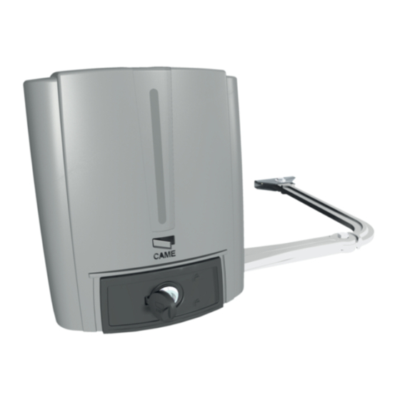
- Page 4 Descrizione delle parti 1. Coperchio 2. Staff a pilastro 3. Spessore in gomma 4. Scheda elettronica 5. Motoriduttore 6. Morsetto di alimentazione 7. Sportello di sblocco 8. Trasformatore 9. Braccio di trasmissione 10. Braccio condotto 11. Staff a cancello 12. Fermi meccanici Impianto tipo 1.
- Page 5 2 x 0,5 mm Antenna RG58 max 10 m Came Remote Protocol (CRP) UTP CAT5 max 1000 m Qualora i cavi abbiano lunghezza diversa rispetto a quanto previsto in tabella, si determini la sezione dei cavi sulla base dell’eff ettivo assorbimento dei dispositivi collegati e secondo le prescrizioni indicate dalla normativa CEI EN 60204-1.
-
Page 6: Installazione
INSTALLAZIONE ⚠ Le seguenti illustrazioni sono solo esempi, in quanto lo spazio per il fissaggio del motoriduttore e degli accessori varia a seconda degli ingombri. Spetta all’installatore scegliere la soluzione più adatta. I disegni si riferiscono all’automazione installata a sinistra. L’installazione del motoriduttore a destra è simmetrica. Posa dei tubi corrugati Predisporre i tubi corrugati necessari per i collegamenti provenienti dal pozzetto di derivazione. - Page 7 Segnare i punti di fissaggio della staffa pilastro e della staffa cancello. Le misure di interasse dei fori delle staffe sono indicate nel paragrafo dimensioni. Forare i punti di fissaggio, inserire i tasselli o utilizzare degli inserti adeguati per la tenuta delle staffe. ...
- Page 8 Fissaggio dell’automazione Inserire il motoriduttore nella staffa pilastro e fissarlo con le viti e i dadi. Inserire la spina nel foro dell’albero motoriduttore. Fissare il braccio di trasmissione all’albero con la rondella per albero lento e la vite. UNI 6593 UNI 5739 Ø...
- Page 9 Sbloccare il motoriduttore (vedi SBLOCCO DEL MOTORIDUTTORE), fissare il braccio condotto alla staffa cancello come indicato nel disegno. Ø 12 UNI 6592 Ø 12 UNI 6593 UNI 5739 Ø 6 M6x10 ⚠ ATTENZIONE! Se non ci sono le battute d’arresto, è obbligatorio fissare i fermi meccanici. Fissaggio dei fermi meccanici Sbloccare il motoriduttore.
- Page 10 Determinazione dei punti di finecorsa Con il motoriduttore sbloccato e con l’anta chiusa, regolare il grano del finecorsa di chiusura girandolo in senso orario o antiorario (). Fissare il grano con il dado (). Allo stesso modo, regolare il finecorsa di apertura sul grano dell’altro fermo ().
- Page 11 COLLEGAMENTI ELETTRICI E PROGRAMMAZIONE ⚠ Attenzione! Prima di intervenire sul quadro comando, togliere la tensione di linea e, se presenti, scollegare le batterie. Tutte le connessioni sono protette da fusibili rapidi. FUSIBILI ZL65 - Linea 2 A-F = 230 V - Accessori 2 A-F Descrizione delle parti...
-
Page 12: Dispositivi Di Comando
Dispositivi di segnalazione 10 11 E 5 M1 N1 ENC1 M2 N2 ENC2 Uscita segnalazione cancello aperto. (Portata contatto 24 V AC/DC - 3 W max). Vedi funzione F 10. Uscita collegamento lampeggiatore o lampada ciclo. (Portata contatto: 24 V AC/DC - 25 W max). Vedi funzione F 18. Dispositivi di comando ATTENZIONE! Prima di inserire una qualsiasi scheda a innesto (es.: AF, R800) è... - Page 13 Collegamento dell’automazione Collegamenti elettrici: automazione installata a sinistra (vista interna). (Predisposizione di default) M1 N1 ENC1 M2 N2 ENC2 Collegamenti elettrici: automazione installata a destra (vista interna). M1 N1 ENC1 M2 N2 ENC2 Collegamento dell’automazione e del motoriduttore Collegamenti elettrici: automazione installata a sinistra e motoriduttore installato a destra (vista interna) con automazione ritardata in chiusura.
- Page 14 Dispositivi di sicurezza Fotocellule Confi gurare il contatto CX o CY (NC), ingresso per dispositivi di sicurezza tipo fotocellule, conformi alla normativa EN 12978. Vedi funzioni ingresso CX (Funzione F2) o CY (Funzione F3) in: - C1 riapertura durante la chiusura. In fase di chiusura del cancello, l’apertura del contatto provoca l’inversione del movimento fi no alla completa apertura;...
- Page 15 ⚠ Nel caso di disturbi di radiofrequenza nell'impianto, il sistema wireless inibisce il normale funzionamento dell'automazione e appare a display l'errore E 17. RIO-EDGE RIO-CELL RIO-LUX RIO-CONN Collegamento con Came Remote Protocol (CRP) Collegamento seriale RS485 con scheda RSE all’impianto domotico via CRP (Came Remote Protocol). Inserire la scheda RSE. UTP CAT 5...
- Page 16 Descrizione dei comandi di programmazione 8 8 8 Display Il tasto ENTER serve per: Il tasto ESC serve per: - entrare nei menu; - uscire dai menu; - confermare e memorizzare il valore impostato. - annullare le modifi che. I tasti < > servono per: - spostarsi da una voce di menu a un’altra;...
- Page 17 Mappatura delle funzioni Funzione stop totale (1-2) Funzione associata all’ingresso 2-CX Funzione associata all’ingresso 2-CY Funzione test sicurezza Funzione azione mantenuta Modalità comando su 2-7 Modalità comando su 2-3P Funzione rilevazione ostacolo a motore fermo F 10 Funzione associata all’uscita segnalazione cancello aperto o abilitazione dell’elettroserratura F 11 Esclusione Encoder F 12...
- Page 18 Menu funzioni IMPORTANTE! Iniziare la programmazione eseguendo per prime le funzioni TIPO MOTORE (A 1), NUMERO MOTORI (F 46) e TARATURA CORSA (A 3). ⚠ La programmazione delle funzioni va eff ettuata con l'automazione ferma. È possibile memorizzare fi no a un max di 25 utenti F 1 Stop totale [1-2] 0 = Disattivata (default) / 1 = Attivata Ingresso NC –...
- Page 19 Uscita sul contatto 10-E. Lampeggiatore: lampeggia durante le fasi di apertura e chiusura del cancello. Ciclo: rimane accesa dall’inizio dell’apertura fi no alla completa chiusura compreso il tempo di attesa prima della chiusura automatica. F 19 Tempo chiusura 0 = Disattivata (default) / 1 = 1 secondo /… / 180 = 180 secondi automatica L’attesa prima della chiusura automatica parte dal raggiungimento del punto di fi...
- Page 20 0 = 1200 Baud / 1 = 2400 Baud / 2 = 4800 Baud / 3 = 9600 Baud / 4 = 14400 Baud / 5 = 19200 Baud / 6 = 38400 Baud / 7 = 57600 Baud / 8 = 115200 Baud Per l’impostazione della velocità di comunicazione utilizzata nel sistema di connessione CRP (Came Remote Protocol). F 65 Ingresso wireless...
- Page 21 RIO-CELL viene associata a una funzione a scelta tra quelle previste: P1 = riapertura durante la chiusura; P2 = richiusura durante l’apertura; P3 = stop parziale; P4 = attesa ostacolo. Per la programmazione, vedi istruzioni allegate all'accessorio. Questa funzione appare solo se nella scheda elettronica è stata inserita una RIO-CONN. U 1 Inserimento utente 1 = Comando passo-passo (apre-chiude) / 2 = Comando sequenziale (apre-stop-chiude-stop) / 3 = Comando solo apre / 4 = Comando parziale...
- Page 22 Taratura corsa Prima di eff ettuare la taratura della corsa, posizionare il cancello a metà corsa, controllare che l’area di manovra sia libera da qualsiasi ostacolo e verifi care la presenza di una battuta d’arresto meccanico in apertura e una in chiusura. ⚠...
- Page 23 Nelle operazioni di inserimento / cancellazione utenti, i numeri lampeggianti visualizzati, sono numeri disponibili e utilizzabili per un eventuale utente da inserire (max 25 utenti). Inserimento utente con comando associato Selezionare U 1. Utente Comando associato Premere ENTER per confermare. Selezionare un comando da associare all’utente.
- Page 24 Scheda Memory Roll Per memorizzare i dati relativi agli utenti e alla confi gurazione dell’impianto, per poi riutilizzarli con un’altra scheda elettronica anche in un altro impianto. Dopo aver memorizzato i dati, è consigliabile togliere la Memory roll. Memory roll. ILLUSTRAZIONE DELLE AREE E PUNTI DI RALLENTAMENTO E DI ACCOSTAMENTO ...
- Page 25 OPERAZIONI FINALI Terminati i collegamenti e la messa in funzione, inserire il coperchio sul motoriduttore (). Fissare il coperchio al motoriduttore e chiudere lo sportello (). Bloccare il motoriduttore con la chiave e inserire il tappo di protezione (). SBLOCCO DEL MOTORIDUTORE ⚠ ...
-
Page 26: Messaggi Di Errore
MESSAGGI DI ERRORE I messaggi di errore sono indicati sul display. La taratura della corsa è stata interrotta dall’attivazione del pulsante di STOP Taratura della corsa incompleta Encoder rotto Errore test servizi Tempo lavoro insuffi ciente Ostacolo in chiusura E 10 Ostacolo in apertura E 11 Numero massimo di ostacoli rilevati E 14 Errore di comunicazione seriale... - Page 27 Fissaggio dei fermi meccanici Sbloccare il motoriduttore. In apertura. Aprire completamente l’anta. Fare un segno sulla cassa in corrispondenza del centro del braccio (). Chiudere manualmente l’anta. Posizionare il fermo meccanico sotto la cassa. Il segno sulla cassa deve corrispondere alla scanalatura sul fermo come illustrato (). Fissare il fermo con la vite ().
- Page 28 Collegamento dell’automazione Collegamenti elettrici: automazione installata a sinistra (vista interna). M1 N1 ENC1 M2 N2 ENC2 Collegamenti elettrici: automazione installata a destra (vista interna). M1 N1 ENC1 M2 N2 ENC2 Collegamento dell’automazione e del motoriduttore Collegamenti elettrici: automazione installata a sinistra e motoriduttore installato a destra (vista interna) con automazione ritardata in chiusura.
-
Page 29: Manutenzione
MANUTENZIONE Manutenzione periodica ☞ Prima di qualsiasi operazione di manutenzione, togliere la tensione, per evitare possibili situazioni di pericolo causate da accidentali movimentazioni del dispositivo. Registro manutenzione periodica a cura dell’utente (semestrale) Data Annotazioni Firma... - Page 30 Manutenzione straordinaria ⚠ La seguente tabella serve per registrare gli interventi di manutenzione straordinaria, di riparazione e di miglioramento eseguiti da ditte esterne specializzate. Gli interventi di manutenzione straordinaria devono essere effettuati da tecnici specializzati. Registro manutenzione straordinaria Timbro installatore Nome operatore Data intervento Firma tecnico...
-
Page 31: Riferimenti Normativi
14001 a garanzia del rispetto e della tutela dell’ambiente. Vi chiediamo di continuare l’opera di tutela dell’ambiente, che CAME considera uno dei fondamenti di sviluppo delle proprie strategie operative e di mercato, semplicemente osservando brevi indicazioni in materia di smaltimento: SMALTIMENTO DELL’IMBALLO... - Page 32 CAME S.p.A. Via Martiri Della Libertà, 15 31030 Dosson di Casier - Treviso - Italy tel. (+39) 0422 4940 - fax. (+39) 0422 4941...
- Page 33 Operator for swing gates FA00095-EN FA7024CB INSTALLATION MANUAL EN English...
- Page 34 HIS PRODUCT SHOULD ONLY BE USED FOR THE PURPOSE FOR WHICH IT WAS EXPLICITLY ONLY MAINTENANCE OPERATION TO DO WITH THE POWER ON ONSTANTLY CLEAN THE . CAME S. DESIGNED NY OTHER USE IS DANGEROUS IS NOT LIABLE FOR ANY DAMAGE •...
- Page 35 LEGEND This symbol shows which parts to read carefully. ⚠ This symbol shows which parts describe safety issues ☞ This symbol shows which parts to tell users about. DESCRIPTION Irreversible operator with control board and segmented graphic display plus jointed transmission-arm for swing gates with leaves up to 2.3 m long. Intended use This operator is designed to power swing gates for residential and apartment block use.
- Page 36 Description of parts 1. Cover 2. Post bracket 3. Rubber shim 4. Control board 5. Gearmotor 6. Power supply terminal 7. Release hatch 8. Transformer 9. Transmission arm 10. Joint arm 11. Gate bracket 12. Mechanical stops Standard installation 1. Operator 2.
- Page 37 Antenna the RG58 antenna max 10 m Came Remote Protocol (CRP) UTP CAT5 max 1000 m If cable lengths diff er from those specifi ed in the table, establish the cable sections depending on the actual power draw of the connected devices and according to the provisions of regulation CEI EN 60204-1.
-
Page 38: Installation
INSTALLATION ⚠ The following illustrations are just examples, in that the space available for fitting the operator and accessories varies depending on the overall dimensions. It is up to the installer to find the most suitable solution. The drawing show an operator fitted on the left. Install the operator on the right, symmetrically. Corrugate tube laying Lay the corrugated tubes you will need for the cables coming out of the junction pit. - Page 39 Marked the spots where the gate-post brace and gate brace will be fitted. The center-distances of the holes on the braces are shown in the Dimensions paragraph. Drill the anchoring points, fit the dowels or use plugs that will hold fast the screws. ...
-
Page 40: Fastening The Operator
Fastening the operator Fit the gearmotor into the gate.post brace and tighten the nuts and bolts. Fit the plug into the gearmotor's drive-shaft hole. Fasten the transmission arm to the drive-shaft using the slow-shaft washer and bolt. UNI 6593 UNI 5739 Ø... - Page 41 Release the gearmotor (see RELEASING THE GEARMOTOR), fit the driven arm to the gate brace as shown in the drawing. Ø 12 UNI 6592 Ø 12 UNI 6593 UNI 5739 Ø 6 M6x10 Fastening the mechanical stops Release the gearmotor. When opening.
- Page 42 Establishing the limit-switch points With the gearmotor released and the gate-leaf closed, adjust the closing limit-switch grub screw by turning it clockwise or counterclockwise (). Tighten the nut to fasten the grub-screw (). In the same way, set the opening limit-switch on the other stop's grub screw ().
- Page 43 ELECTRICAL CONNECTIONS AND PROGRAMMING ⚠ Warning! Before working on the control panel, cut off the main current supply and, if present, remove any batteries. All connections are quick-fuse protected. FUSES ZL65 - Line 2 A-F = 230 V - Accessories 2 A-F Description of parts Terminals for signaling devices...
-
Page 44: Command And Control Devices
Signaling devices 10 11 E 5 M1 N1 ENC1 M2 N2 ENC2 Gate-open signal output. (Contact rated for 24 V AC/DC - 3 W max). See function F 10. Output for connecting either fl ashing or cycle light. (Contact rated for: 24 V AC/DC - 25 W max). See function F 18. Command and control devices WARNING! For the system to work properly, before fitting any plug-in card, such as the AF or R800 one, you MUST CUT OFF THE MAINS POWER SUPPLY and, if present, disconnect any batteries. - Page 45 Connecting the operator Electrical connections: Operator installed on the left (outer view). (Default setting) M1 N1 ENC1 M2 N2 ENC2 Electrical connections: operator fi tted on the right (inner view). M1 N1 ENC1 M2 N2 ENC2 Connecting the operator and gearmotor Electrical connections: operator installed to the left and gearmotor installed to the right (inner view) with operator delayed when...
- Page 46 Safety devices Photocells Confi gure contact CX or CY (NC), input for safety devices, such as photocells, that comply with EN 12978 provisions. See CX input functions (Function F2) or CY (Function F3) in: - C1 reopening during closing. when the gate is closing, opening the contact causes the inversion of movement until opening is complete; - C2 close back up during opening.
-
Page 47: Wireless Devices
⚠ If the system has radiofrequency interferences, the wireless system will inhibit the operator's normal operating mode and the E 17 error message is displayed. RIO-EDGE RIO-CELL RIO-LUX RIO-CONN Connection with Came Remote Protocol (CRP) Serial connection of the RS485 with RSE card to the home & building automation system via CRP (Came Remote Protocol). Fit the RSE card. UTP CAT 5... -
Page 48: Description Of Programming Commands
Description of programming commands 8 8 8 Display The ENTER key is for: The ESC button is for: - entering menus; - exiting menus; - confi rming or memorizing set values. - cancelling changes. The < > keys are for: - moving from one item to another;... - Page 49 Functions map Total stop function (1-2) Function associated to input 2-CX Function associated to input 2-CY Safety test function Maintained action function Control mode on 2-7 Control mode on 2-3P Obstruction detection with motor idle function F 10 Function associated to the open gate signal or electric lock enabling. F 11 Encoder exclusion F 12...
- Page 50 Functions menu IMPORTANT! Start programming by fi rst performing functions MOTOR TYPE (A1), NUMBER OF MOTORS (F46), MOTORS TEST (A2) and TRAVEL CALIBRATION (A3). ⚠ Programming the features is to be done when the operator is stopped. You can memorize up to 25 users. F 1 Total stop [1-2] 0 = Deactivated (default) / 1 = Activated NC input –...
- Page 51 The automatic-closing wait starts when the opening limit switch point is reached and can be set to between 1 and 180 seconds. The automatic closing does not turn on if any of the safety devices trigger when an obstruction is detected, after a total stop or during a power outage. F 20 Automatic closing time 0 = Deactivated (default) / 1 = 1 second /…...
- Page 52 0 = 1200 Baud / 1 = 2400 Baud / 2 = 4800 Baud / 3 = 9600 Baud / 4 = 14400 Baud / 5 = 19200 Baud / 6 = 38400 Baud / 7 = 57600 Baud / 8 = 115200 Baud For setting the communication speed used in the CRP (Came Remote Protocol) connection system. F 65 Wireless input RIO-EDGE...
- Page 53 U 1 Entering a user 1 = Step-step command (open-close) / 2 = Sequential command (open-stop-close-stop) / 3 = Only open command / 4 = Partial command Entering up to up to a 25 users maximum and associating to each one a function chosen among the existing ones. This must be done via transmitter or other control device (see "ENTERING USERS WITH ASSOCIATED COMMAND paragraph).
-
Page 54: Travel Calibration
Travel calibration Before calibrating the gate travel, position the gate half-way, check that the maneuvering area is clear of any obstruction and check that there are mechanical opening and closing stops. ⚠ The mechanical end-stops are obligatory. Important! During calibration, all safety devices will be disabled. Select A 3. - Page 55 When entering/deleting users, the fl ashing numbers that appear, are numbers that can be used for other users you may wish to enter (maxi- mum 25 users). Entering a user with an associated command Select U 1 User Associated command Press ENTER to confi...
- Page 56 Memory Roll Card To memorize user data and confi gure the system, to then reuse them with another control board even on another system. After memorizing the data, it is best to remove the Memory roll. Memory roll. ILLUSTRATION OF THE SLOW-DOWN AND APPROACH AREAS AND POINTS ...
-
Page 57: Final Operations
FINAL OPERATIONS Once you have fi nished with the connections and started up the operator, fi t the casing over the gearmotor (). Fit the casing over the gearmotor and close the hatch (). Lock the gearmotor using the key and fi t the protection cap (). RELEASING THE GEARMOTOR ⚠ ... -
Page 58: Error Message
ERROR MESSAGE The error messages are shown on the display. The travel calibration was interrupted when the STOP button was activated Calibrating the incomplete travel Encoder broken Services test error Insuffi cient working time Closing obstruction E 10 Opening obstruction E 11 Maximum number of detected obstructions E 14 Serial communication error E 17 Wireless system error... - Page 59 Fastening the mechanical stops Release the gearmotor. When opening. Entirely open the gate leaf. Mark the casing where the center of the arm is.(). Manually close the gate leaf. Place the mechanical stop under the casing. The mark on the case must match the groove on the stop, as shown().
- Page 60 Connecting the operator Electrical connections: Operator installed on the left (outer view). M1 N1 ENC1 M2 N2 ENC2 Electrical connections: operator fi tted on the right (inner view). M1 N1 ENC1 M2 N2 ENC2 Connecting the operator and gearmotor Electrical connections: operator installed to the left and gearmotor installed to the right (inner view) with operator delayed when closing.
-
Page 61: Maintenance
MAINTENANCE Periodic maintenance ☞ Before doing any maintenance, cut off the power supply, to prevent any hazardous situations caused by accidentally activating the operator. Periodic maintenance log kept by users (every six months) Date Notes Signature... - Page 62 Extraordinary maintenance ⚠ The following table is for logging any extraordinary maintenance jobs, repairs and improvements performed by specialized contractors. Any extraordinary maintenance jobs must be done only by specialized technicians. Extraordinary maintenance log Fitter's stamp Name of operator Job performed on (date) Technician's signature Requester's signature...
-
Page 63: Dismantling And Disposal
DISMANTLING AND DISPOSAL ☞ CAME S.p.A. applies a certified Environmental Management System at its premises, which is compliant with the UNI EN ISO 14001 standard to ensure the environment is safeguarded. Please continue safeguarding the environment. At CAME we consider it one of the fundamentals of our operating and market strategies. Simply... - Page 64 CAME S.p.A. Via Martiri Della Libertà, 15 31030 Dosson di Casier - Treviso - Italy tel. (+39) 0422 4940 - fax. (+39) 0422 4941...
- Page 65 Automatisme pour portails battants FA00095-FR FA7024CB MANUEL D’INSTALLATION FR Français...
- Page 66 ATTENTION ! Instructions importantes pour la sécurité des personnes : À LIRE ATTENTIVEMENT ! VANT PROPOS APPAREIL E NETTOYAGE ET L ENTRETIEN QUE DOIT EFFECTUER L UTILISATEUR NE DOIVENT • C PAS ÊTRE CONFIÉS À DES ENFANTS LAISSÉS SANS SURVEILLANCE ONTRÔLER SOUVENT •...
- Page 67 LÉGENDE Ce symbole indique des parties à lire attentivement. ⚠ Ce symbole indique des parties concernant la sécurité. ☞ Ce symbole indique ce qui doit être communiqué à l'utilisateur. DESCRIPTION Automatisme irréversible avec carte électronique, affi cheur à segments et bras de transmission articulé pour portails battants jusqu'à 2,3 m par vantail.
- Page 68 Description des parties 1. Couvercle 2. Étrier pilier 3. Entretoise en caoutchouc 4. Carte électronique 5. Motoréducteur 6. Borne d'alimentation 7. Volet de déblocage 8. Transformateur 9. Bras de transmission 10. Bras courbé 11. Étrier portail 12. Butées mécaniques Installation standard 1.
- Page 69 2 x 0,5 mm Antenne RG58 max 10 m Came Remote Protocol (CRP) UTP CAT5 max 1000 m Si la longueur des câbles ne correspond pas aux valeurs indiquées dans le tableau, déterminer la section des câbles en fonction de l’absorption eff ective des dispositifs connectés et selon les prescriptions de la norme CEI EN 60204-1.
- Page 70 INSTALLATION ⚠ Les illustrations suivantes ne sont que des exemples étant donné que l'espace pour la fixation du motoréducteur et des accessoires varie en fonction des encombrements. C'est donc l'installateur qui doit choisir la solution la plus indiquée. Les dessins illustrent l'automatisme installé à gauche. L’installation du motoréducteur à droite est symétrique. Pose des gaines annelées Prévoir les gaines annelées nécessaires pour les raccordements issus du boîtier de dérivation.
- Page 71 Noter les points de fixation de l'étrier pilier et de l'étrier portail. Les cotes d'entraxe des trous des étriers sont indiquées au paragraphe dimensions. Percer les points de fixation, introduire les chevilles ou utiliser des éléments adéquats pour la fixation des étriers. ...
- Page 72 Fixation de l'automatisme Introduire le motoréducteur dans l'étrier pilier et le fixer à l'aide des vis et des écrous. Introduire la cheville dans le trou de l'arbre du motoréducteur. Fixer le bras de transmission à l'arbre à l'aide de la rondelle pour arbre lent et de la vis. UNI 6593 UNI 5739 Ø...
- Page 73 Débloquer le motoréducteur (voir DÉBLOCAGE DU MOTORÉDUCTEUR), fixer le bras courbé à l'étrier de fixation au portail comme indiqué sur le dessin. Ø 12 UNI 6592 Ø 12 UNI 6593 UNI 5739 Ø 6 M6x10 Fixation des butées mécaniques Débloquer le motoréducteur. En phase d'ouverture.
- Page 74 Détermination des points de fin de course Avec motoréducteur débloqué et vantail fermé, régler le goujon de la butée de fin de course de fermeture en le tournant dans le sens horaire ou anti-horaire (). Fixer le goujon à l'aide de l'écrou (). Régler de la même manière la butée de fin de course d'ouverture en intervenant sur le goujon de l'autre butée ().
- Page 75 BRANCHEMENTS ÉLECTRIQUES ET PROGRAMMATION ⚠ Attention ! Avant d'intervenir sur l'armoire de commande, mettre hors tension et déconnecter les éventuelles batteries. Toutes les connexions sont protégées par des fusibles rapides. FUSIBLES ZL65 - Ligne 2 A-F = 230 V - Accessoires 2 A-F Description des parties Bornier de connexion des dispositifs de signalisation...
- Page 76 Dispositifs de signalisation 10 11 E 5 M1 N1 ENC1 M2 N2 ENC2 Sortie signalisation portail ouvert. (Portée contact 24 VAC/DC - 3 W max.). Voir fonction F 10. Sortie connexion feu clignotant ou lampe cycle. (Portée contact : 24 VAC/DC - 25 W max.). Voir fonction F 18. Dispositifs de commande ATTENTION ! Avant l'insertion d'une carte enfichable (ex.
- Page 77 Connexion de l'automatisme Branchements électriques : automatisme installé à gauche (vue interne). (Installation par défaut) M1 N1 ENC1 M2 N2 ENC2 Branchements électriques : automatisme installé à droite (vue interne). M1 N1 ENC1 M2 N2 ENC2 Connexion de l'automatisme et du motoréducteur Branchements électriques : automatisme installé...
- Page 78 Dispositifs de sécurité Photocellules Confi gurer le contact CX ou CY (NF), entrée pour dispositifs de sécurité, type photocellules, conformes à la norme EN 12978. Voir fonctions entrée CX (Fonction F2) ou CY (Fonction F3) en : - C1 pour la réouverture durant la fermeture. Durant la phase de fermeture du portail, l'ouverture du contact provoque l'inversion du mouvement jusqu'à...
- Page 79 ⚠ En cas de brouillages de radiofréquence au niveau de l'installation, le système sans fi l désactive le fonctionnement normal de l'automatisme et l'écran affi che l'erreur E 17. RIO-EDGE RIO-CELL RIO-LUX RIO-CONN Connexion avec Came Remote Protocol (CRP) Connexion série RS485 avec carte RSE à l'installation domotique via CRP (Came Remote Protocol). Insérer la carte RSE. UTP CAT 5...
-
Page 80: Navigation Menu
Description des commandes de programmation 8 8 8 Affi cheur La touche ENTER permet de/d' : La touche ESC permet de/d' : - entrer dans les menus - sortir des menus - confi rmer et mémoriser la valeur confi gurée. - annuler les modifi... - Page 81 Mappage des fonctions Fonction arrêt total (1-2) Fonction associée à l'entrée 2-CX Fonction associée à l'entrée 2-CY Fonction test sécurité Fonction action maintenue Modalité commande sur 2-7 Modalité commande sur 2-3P Fonction détection obstacle avant démarrage F 10 Fonction associée à la sortie signalisation portail ouvert ou activation de la serrure électrique F 11 Désactivation Encodeur F 12...
- Page 82 Menu fonctions IMPORTANT ! Lancer la programmation à partir des fonctions de TYPE MOTEUR (A1), NOMBRE MOTEURS (F46), TEST MOTEURS (A2) et RÉGLAGE COURSE (A3). ⚠ Pour eff ectuer la programmation des fonctions, l'automatisme doit être à l'arrêt. Il est possible de mémoriser au maximum 25 utilisateurs F 1 Arrêt total [1-2] 0 = Désactivée (par défaut) / 1 = Activée Entrée NF –...
- Page 83 F 19 Temps fermeture automatique 0 = Désactivée (par défaut) / 1 = 1 seconde /… / 180 = 180 secondes L’attente avant la fermeture automatique démarre lorsque le point de fi n de course a été atteint en phase d'ouverture pendant un délai réglable entre 1 et 180 secondes.
- Page 84 Bauds / 6 = 38400 Bauds / 7 = 57600 Bauds / 8 = 115200 Bauds Pour la confi guration de la vitesse de communication utilisée dans le système de connexion CRP (Came Remote Protocol). F 65 Entrée sans fi l RIO-EDGE [T1] 0 = Désactivée (par défaut) / 7 = P7 / 8 = P8 Dispositif de sécurité...
- Page 85 U 2 Élimination utilisateur Élimination d'un seul utilisateur (voir paragraphe ÉLIMINATION D'UN SEUL UTILISATEUR). U 3 Élimination utilisateurs 0 = Désactivée / 1 = Élimination de tous les utilisateurs Élimination de tous les utilisateurs. A 1 Type moteur défaut) / 2 = FA7024CB 1 = SWN20 - SWN25 (par Sélection du motoréducteur utilisé...
- Page 86 Auto-apprentissage de la course Avant de régler la course, amener le portail à mi-course, s'assurer que la zone d'actionnement ne présente aucun obstacle et s'assurer de la présence d'une butée d'arrêt mécanique aussi bien à l'ouverture qu'à la fermeture. ⚠...
- Page 87 Les numéros clignotants qui apparaissent durant les opérations d'insertion et d'élimination des utilisateurs sont disponibles et utilisables pour un éventuel utilisateur à insérer (max. 25 utilisateurs). Insertion utilisateur avec commande associée Sélectionner U 1. Utilisateur Commande associée Appuyer sur ENTER pour confi rmer. Sélectionner une commande à...
- Page 88 Carte de mémoire Pour mémoriser les données relatives aux utilisateurs et à la confi guration de l'installation de manière à ce qu'elles soient réutilisables sur une autre carte électronique, voire une autre installation. Après avoir mémorisé les données, il vaut mieux enlever la Memory roll. Memory roll.
- Page 89 OPÉRATIONS FINALES Au terme des branchements et de la mise en fonction, remettre le couvercle sur le motoréducteur (). Fixer le couvercle au motoréducteur et fermer le volet (). Bloquer le motoréducteur à l'aide de la clé et appliquer le capuchon de protection (). DÉBLOCAGE DU MOTORÉDUCTEUR ⚠ ...
-
Page 90: Messages D'erreur
MESSAGES D'ERREUR Les messages d'erreur apparaissent à l'écran. L'auto-apprentissage de la course a été interrompu par l'activation du bouton d'ARRÊT Auto-apprentissage de la course incomplet Encodeur cassé Erreur test services Temps de fonctionnement insuffi sant Obstacle à la fermeture E 10 Obstacle à l'ouverture E 11 Nombre maximum d'obstacles détectés E 14 Erreur de communication série E 17 Erreur du système sans fi... - Page 91 Fixation des butées mécaniques Débloquer le motoréducteur. En phase d'ouverture. Ouvrir complètement le vantail. Tracer une ligne au crayon sur la caisse au niveau du centre du bras (). Fermer manuellement le vantail. Positionner la butée mécanique sous la caisse. Le signe sur la caisse doit correspondre à...
- Page 92 Connexion de l'automatisme Branchements électriques : automatisme installé à gauche (vue interne). M1 N1 ENC1 M2 N2 ENC2 Branchements électriques : automatisme installé à droite (vue interne). M1 N1 ENC1 M2 N2 ENC2 Connexion de l'automatisme et du motoréducteur Branchements électriques : automatisme installé...
-
Page 93: Entretien
ENTRETIEN Entretien périodique ☞ Avant toute autre opération d'entretien, il est conseillé de mettre hors tension pour éviter toute situation de danger provoquée par des déplacements accidentels du dispositif. Registre d'entretien périodique tenu par l'utilisateur (semestriel) Date Remarques Signature... - Page 94 Entretien curatif ⚠ Le tableau suivant permet d'enregistrer les interventions d'entretien curatif, de réparation et d'amélioration effectuées par des sociétés externes spécialisées. Les interventions d'entretien curatif doivent être effectuées par des techniciens qualifiés. Registre entretien curatif Cachet installateur Nom opérateur Date intervention Signature technicien Signature client...
- Page 95 MISE AU REBUT ET ÉLIMINATION ☞ CAME S.p.A. adopte dans ses établissements un Système de Gestion Environnementale certifié et conforme à la norme UNI EN ISO 14001 qui garantit le respect et la sauvegarde de l'environnement. Nous vous demandons de poursuivre ces efforts de sauvegarde de l'environnement, que CAME considère comme l'un des fondements du développement de ses propres stratégies opérationnelles et de marché, en observant tout simplement de brèves indications en matière d'élimination :...
- Page 96 CAME S.p.A. Via Martiri Della Libertà, 15 31030 Dosson di Casier - Treviso - Italy tel. (+39) 0422 4940 - fax. (+39) 0422 4941...
- Page 97 Aвтоматика для распашных ворот FA00095-RU FA7024CB ИНСТРУКЦИЯ ПО МОНТАЖУ RU Русский...
- Page 98 . Л КОМПАНИИ Е ПОЗВОЛЯЙТЕ ДЕТЯМ ИГРАТЬ С АВТОМАТИКОЙ АБОТЫ ПО ЧИСТКЕ И ТО ИЗДЕЛИЕ ДОЛЖНО ИСПОЛЬЗОВАТЬСЯ ИСКЛЮЧИТЕЛЬНО ПО НАЗНАЧЕНИЮ ЮБОЕ . CAME S. ТЕХНИЧЕСКОМУ ОБСЛУЖИВАНИЮ КОТОРЫЕ ДОЛЖЕН ВЫПОЛНЯТЬ ПОЛЬЗОВАТЕЛЬ НЕЛЬЗЯ ДРУГОЕ ПРИМЕНЕНИЕ РАССМАТРИВАЕТСЯ КАК ОПАСНОЕ СНИМАЕТ С • С...
-
Page 99: Условные Обозначения
УСЛОВНЫЕ ОБОЗНАЧЕНИЯ Этот символ обозначает раздел, требующий особого внимания. ⚠ Этот символ обозначает раздел, связанный с вопросами безопасности. ☞ Этот символ обозначает раздел, предназначенный для ознакомления конечного пользователя. ОПИСАНИЕ Самоблокирующийся привод, укомплектованный блоком управления с радиодекодером, дисплеем и шарнирным рычагом передачи, для створок... - Page 100 Основные компоненты 1. Крышка 2. Задний кронштейн 3. Резиновый уплотнитель 4. Плата блока управления 5. Привод 6. Контакты электропитания 7. Дверца разблокировки 8. Трансформатор 9. Передающий рычаг 10. Рычаг-труба 11. Передний кронштейн 12. Механические упоры Вариант типовой установки 1. Привод 2.
-
Page 101: Предварительные Проверки
2 x 0,5 мм Антенна RG58 макс. 10 м Came Remote Protocol (CRP) UTP CAT5 макс. 1000 м Если длина кабеля отличается от приведенной в таблице, его сечение определяется на основании реального потребления тока подключенными устройствами и в соответствии с указаниями, содержащимися в нормативе CEI EN 60204-1. - Page 102 МОНТАЖ ⚠ Приведенные ниже рисунки носят иллюстративный характер, так как пространство для крепления автоматики и дополнительных принадлежностей может меняться от случая к случаю. Выбор наиболее подходящего решения должен осуществляться установщиком на месте. Рисунки иллюстрируют монтаж левосторонней автоматики. Монтаж правого привода выполняется симметрично. Прокладка...
- Page 103 Обозначьте места крепления переднего и заднего кронштейнов. Расстояние между отверстиями кронштейнов приведено в разделе "Габаритные и установочные размеры". Просверлите крепежные отверстия, вставьте дюбели или используйте вкладыши, подходящие для крепежа пластин. Все рисунки носят исключительно иллюстративный характер, поэтому выбор наиболее подходящего решения осуществляется установщиком...
- Page 104 Крепление автоматики Вставьте привод в задний кронштейн и зафиксируйте его с помощью винтов и гаек. Вставьте штифт в отверстие приводного вала. Прикрепите рычаг к приводному валу с помощью шайбы, предназначенной для медленновращающегося вала, и винта. UNI 6593 UNI 5739 Ø 14 M10x14 Прикрепите...
- Page 105 Разблокируйте привод (см. раздел "РАЗБЛОКИРОВКА ПРИВОДА"), прикрепите рычаг-трубу к переднему кронштейну, как показано на рисунке. Ø 12 UNI 6592 Ø 12 UNI 6593 UNI 5739 Ø 6 M6x10 Монтаж механических концевых выключателей Разблокируйте привод. При открывании: Полностью откройте створку. Отметьте на корпусе место, соответствующее центру рычага (). Закройте...
- Page 106 Регулировка крайних положений Разблокировав привод и полностью закрыв створку ворот, отрегулируйте конечное положение закрывания, вращая установочный винт по часовой стрелке и обратно (). Зафиксируйте винт с помощью гайки (). Аналогичным образом отрегулируйте конечное положение открывания, вращая винт другого концевого выключателя ().
- Page 107 ЭЛЕКТРИЧЕСКИЕ ПОДКЛЮЧЕНИЯ И ПРОГРАММИРОВАНИЕ ⚠ Внимание! Перед началом работ по эксплуатации, ремонту, настройке и регулировке блока управления отключите сетевое электропитание и/или отсоедините аккумуляторы. Все подключения защищены плавкими предохранителями. ПРЕДОХРАНИТЕЛЕЙ ZL65 - Входной 2 A-F = 230 В - Аксессуары Основные компоненты Контакты...
- Page 108 Устройства сигнализации 10 11 E 5 M1 N1 ENC1 M2 N2 ENC2 Лампа-индикатор "Вороты открыты" (макс. нагрузка контакта ~/=24 В ― 3 Вт) См. настройки функции "F 10". Выход подключения сигнальной лампы или лампа цикла. (Макс. нагрузка: ~/=24 В, 25 Вт). См. настройки функции "F 18". Устройства...
- Page 109 Подключение автоматики Электрические подключения: автоматика, установленная слева (вид изнутри). (Подключение по умолчанию) M1 N1 ENC1 M2 N2 ENC2 Электрические подключения: автоматика, установленная справа (вид изнутри). M1 N1 ENC1 M2 N2 ENC2 Подключение автоматики и привода Электрические подключения: левосторонняя автоматика и установленный справа...
- Page 110 Устройства безопасности Фотоэлементы Выполните конфигурацию контактов CX или CY (Н.З.), предназначенных для подключения устройств безопасности, например, фотоэлементов, соответствующих требованиям норматива EN 12978. Режим работы контактов CX (Функция F2) или CY (Функция F3) выбирается в меню "Функции". Могут быть выбраны следующие режимы работы: - C1: "Открывание...
- Page 111 ⚠ В случае радиопомех беспроводная система блокирует нормальную работу автоматики, а на дисплее появляется сообщение об ошибке "E17". RIO-EDGE RIO-CELL RIO-LUX RIO-CONN Подключение к Came Remote Protocol (CRP) Последовательное подключение RS485 с платой RSE к "умному дому" посредством CRP (Came Remote Protocol). Вставьте плату RSE. UTP CAT 5...
- Page 112 Описание устройств программирования 8 8 8 Дисплей Кнопка "ВВОД" (ENTER) служит для: Кнопка "ВЫХОД" (ESC) служит - входа в меню; для: - подтверждения и сохранения значения вы- - выхода из меню; бранного параметра. - отмены выбора. Кнопки < > служат для: - перемещения...
- Page 113 Таблица функций Функция "Стоп" (1-2) Функция, присвоенная входным контактам 2-CX Функция, присвоенная входным контактам 2-CY Функция самодиагностики устройств безопасности Функция управления в режиме "Присутствие оператора" Режим управления для контактов 2-7 Режим управления для контактов 2-3P Функция обнаружения препятствия при остановленном приводе F 10 Лампа-индикатор...
- Page 114 Меню "Функции" ВАЖНО! Начните программирование с функций "МОДЕЛЬ ПРИВОДА" (A 1), "КОЛИЧЕСТВО ПРИВОДОВ" (F46), "ТЕСТ ПРИВОДОВ" (A2) и "КАЛИБРОВКА ДВИЖЕНИЯ" (А3). ⚠ Программирование можно выполнять, только когда автоматика не работает. В памяти можно сохранить до 25 пользователей. F 1 Функция "Стоп" [1-2] 0 = Отключена...
- Page 115 Контактный выход 10-E. Сигнальная лампа мигает во время движения ворот. Режим ламы цикла: светодиодная лампа остается включенной от начала открывания до полного закрывания ворот, включая время ожидания перед автоматическим закрыванием. F 19 Время автоматического закрывания 0 = Отключена (по умолчанию) / 1 = 1 секунда / … / 180 = 180 секунд Время...
- Page 116 0 = 1200 бод / 1 = 2400 бод / 2 = 4800 бод / 3 = 9600 бод / 4 = 14400 бод / 5 = 19200 бод / 6 = 38400 бод / 7 = 57600 бод / 8 = 115200 бод Регулировка скорости обмена данными в системе подключений CRP (Came Remote Protocol). F65 Беспроводное соединение...
- Page 117 RIO-CELL присваивается одна из следующих функций на выбор: P1 = открывание в режиме закрывания; P2 = закрывание во время открывания; P3 = частичный стоп; P4 = обнаружение препятствия. Для программирования смотрите инструкции, прилагаемые к устройству. Эта функция доступна только в том случае, если в плату блока управления вставлена плата RIO-CONN. U 1 Создание...
- Page 118 Калибровка движения Перед тем как отрегулировать движение створок, установите ворота в средней точке траектории движения, убедитесь в отсутствии каких-либо препятствий и наличии механических упоров открывания и закрывания. ⚠ Использование механических упоров является обязательным. Важно! Во время калибровки все устройства безопасности будут отключены. Выберите...
- Page 119 При создании/удалении пользователей на дисплее отображаются мигающие числа, указывающие на свободные номера ячеек памя- ти, которые могут быть использованы для добавления новых пользователей (макс. 25 пользователей). Добавление пользователей с разными функциями управления Выберите “U1”. Пользователь Присвоенная команда Подтвердите, нажав "ВВОД" (ENTER). Выберите...
- Page 120 Карта памяти Карта памяти необходима для запоминания данных о пользователях и настройках системы, а также их последующего использования на другой системе с помощью другой платы управления. После сохранения данных рекомендуется вытащить карту памяти. Карта памяти ИЛЛЮСТРАЦИЯ УЧАСТКОВ И ТОЧЕК НАЧАЛА ЗАМЕДЛЕНИЯ И ОСТАНОВКИ СТВОРОК ...
-
Page 121: Заключительные Работы
ЗАКЛЮЧИТЕЛЬНЫЕ РАБОТЫ После выполнения всех электрических подключений и подготовки системы к работе установите крышку на привод (). Зафиксируйте крышку привода и закройте дверцу (). Закройте дверцу, заблокируйте привод с помощью ключа и установите защитную крышку (). РАЗБЛОКИРОВКА ПРИВОДА ⚠ Перед выполнением операции обесточьте систему. ⚠ ... -
Page 122: Сообщения Об Ошибках
СООБЩЕНИЯ ОБ ОШИБКАХ Сообщения об ошибках отображаются на дисплее. Калибровка движения прервана из-за нажатия кнопки "СТОП" Калибровка движения незавершена Энкодер неисправен Ошибка самодиагностики Недостаточное время работы Препятствие при закрывании E 10 Препятствие при открывании E 11 Максимальное количество обнаруженных препятствий E 14 Ошибка... - Page 123 Монтаж механических упоров Разблокируйте привод. При открывании: Полностью откройте створку. Отметьте на корпусе место, соответствующее центру рычага (). Закройте створку вручную. Установите механический упор под корпус. Оставленная на корпусе отметина должна соответствовать пазу на упоре, как показано на рисунке (). Зафиксируйте...
- Page 124 Подключение автоматики Электрические подключения: автоматика, установленная слева (вид изнутри). M1 N1 ENC1 M2 N2 ENC2 Электрические подключения: автоматика, установленная справа (вид изнутри). M1 N1 ENC1 M2 N2 ENC2 Подключение автоматики и привода Электрические подключения: левосторонняя автоматика и установленный справа привод (вид изнутри) с задержкой авто- матики...
-
Page 125: Техническое Обслуживание
ТЕХНИЧЕСКОЕ ОБСЛУЖИВАНИЕ Периодическое техническое обслуживание ☞ Перед выполнением работ по техническому обслуживанию отключите питание во избежание возникновения опасных ситуаций, вызванных непроизвольным движением устройства. Журнал периодического технического обслуживания, заполняемый пользователем (каждые 6 месяцев) Дата Выполненные работы Подпись... - Page 126 Внеплановое техническое обслуживание и ремонт ⚠ Эта таблица необходима для записи внеплановых работ по обслуживанию и ремонту оборудования, выполненных специализированными предприятиями. Ремонт оборудования должен осуществляться квалифицированными специалистами. Бланк регистрации работ по внеплановому техническому обслуживанию Место печати Компания Дата проведения работ Подпись...
- Page 127 УТИЛИЗАЦИЯ ☞ CAME S.p.A. имеет сертификат системы защиты окружающей среды UNI EN ISO 14001, гарантирующий экологическую безопасность на ее заводах. Мы просим, чтобы вы продолжали защищать окружающую среду. САМЕ считает одним из фундаментальных пунктов стратегии рыночных отношений выполнение этих кратких руководящих принципов: УТИЛИЗАЦИЯ...
- Page 128 CAME S.p.A. Via Martiri Della Libertà, 15 31030 Dosson di Casier - Treviso - Italy tel. (+39) 0422 4940 - fax. (+39) 0422 4941...
Need help?
Do you have a question about the FAST 70 and is the answer not in the manual?
Questions and answers