Table of Contents
Advertisement
Quick Links
SYSTEM 2000 BOILER - PRINCIPLE OF OPERATION
SYSTEM 2000 comprises a heat source, the energy converter, circulating water, and five (or more) zones controlled
by an electronic control, the Digital Manager.
The Boiler sits cold until a thermostat calls for heat. The Digital Manager receives the call for heat and turns on the
main circulator and burner. Water circulates within the boiler as it warms up to operating temperature. When ready, the
zone valves open and deliver heat to the zones calling for heat. When the thermostats are satisfied, the Digital Manager
turns off the burner and enters the energy recovery stage. The circulator and zone valve stay energized to deliver the
heat remaining in the boiler to your home or to the domestic hot water storage tank.
When energy recovery is complete and the Boiler has been cooled off, the Digital Manager turns off the system and
waits for another thermostat (or tank aquastat) to call for heat. SYSTEM 2000 runs the burner only when you need heat
and delivers that heat only where you need heat.
The System 2000 Energy Converter is the product of advanced thermal engineering. It is designed with two separate
passageways, nearly 10 feet long, coiled around each other. Water travels along one passageway from your home
toward the center of the unit and heated gases travel from the unit center toward the chimney. This is a "forced circulation
counter-flow" design and it provides very efficient transfer of heat from the burning fuel to the circulating water. The
superior insulation of the boiler minimizes heat losses to the surroundings, resulting in directing heat to your home in an
efficient and quiet manner.
SYSTEM 2000 has an extremely high annual efficiency (over 99% of steady state) because it runs only when your
home or hot water storage tank needs heat. Energy recovery is completed at the end of each heat call, virtually eliminating
off cycle losses.
Your System 2000 holds a minimal quantity of water so it begins to supply heat in about 90 seconds. This rapid
response means that your rooms can be heated quickly to temperature. The System 2000 EK1 Frontier can heat water up
to 100,000 BTU's per hour and the EK2 Frontier up to 200,000 BTU/hr.
A modern retention head oil burner fires into the center of System 2000 where a high temperature, light weight
ceramic chamber provides ideal conditions for "near perfect" efficient, pollution-free combustion. Your System 2000 is
tightly sealed so all products of combustion pass only to the chimney or sidewall vent.
The FRONTIER Boiler is designed with a hinged front cover that allows access to the inside of the boiler for inspection
and cleaning. All access for service is from the front, so the FRONTIER Boiler can be placed directly against a wall or into
a closet.
DIGITAL MANAGER - PRINCIPLE OF OPERATION
(See Section E, Digital Manager for detailed trouble shooting and diagnostics)
The left side of the Manager is the input side, which provides 24-volt power supply and connections for thermostats.
The right side is the output side, which starts the burner, circulator, zone valves or zone circulators and the domestic hot
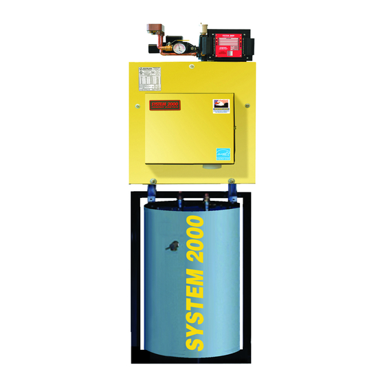
water circulator. See photo of the Manager on the cover.
Lights on the Digital Manager indicate what is calling for heat (left side) and (right side) lights indicate active zone(s),
burner operation and circulator operation. These function lights are an aid in servicing. The following is a typical cycle.
1. SYSTEM WAITING FOR A CALL: The boiler is turned off and sits cold, waiting until a call for heat. The red power
light on the Manager is glowing.
2. CALL FOR HEAT: A room thermostat call starts the cycle. The thermostat light on the left side will turn on for that
zone.
3. PRE-HEAT: Output lights for the main circulator and burner turn on, the circulator starts, and the burner begins firing.
The boiler water circulates through the energy converter via the bypass line, heating up the water.
4. HEAT: Once the boiler water has heated up to 140F (about 90 seconds), the Manager will turn on the zone output
light on the right side. The zone valve will open and hot water will flow to the zone needing heat. The burner runs as
long as there is a thermostat calling and as long as heat is being delivered to the zone. The burner may shut off if the
return temperature exceeds 170F/190F (RED burner light turns off) or if the high limit temperature is exceeded (RED
burner light stays on, but the high limit aquastat shuts the burner off).
5. ANOTHER CALL FOR HEAT: If another zone calls for heat while the burner is already running and the return
temperature is above 140F, the zone output will turn on, immediately supplying heat to the zone.
6. MONITOR RETURN TEMPERATURE: The Manager continually senses the return temperature and will turn off the
zone outputs if the return temperature drops below 120
closed, the boiler water will quickly reheat and once the return temperature reaches 140
is ON), then the Manager will reopen the zone valves.
7. THERMOSTAT SATISFIED: The thermostat light on the left side will go out. The burner light and the burner will then
turn off.
B1-1
FRONTIER BOILER
Instructions, Service Version, Oilheat Edition
o
o
F (130
F if Option Switch #1 is ON). With the zone outputs
o
o
F (150
F if Option Switch #1
Advertisement
Table of Contents

Related Manuals for ENERGY KINETICS System 2000 Frontier


Summary of Contents for ENERGY KINETICS System 2000 Frontier
- Page 1 FRONTIER BOILER Instructions, Service Version, Oilheat Edition SYSTEM 2000 BOILER - PRINCIPLE OF OPERATION SYSTEM 2000 comprises a heat source, the energy converter, circulating water, and five (or more) zones controlled by an electronic control, the Digital Manager. The Boiler sits cold until a thermostat calls for heat. The Digital Manager receives the call for heat and turns on the main circulator and burner.
-
Page 2: Receiving And Unpacking
Place the unit as near to the chimney or vent as possible allowing clearance for front cleaning and service as shown in Figure 1B. If not using an Energy Kinetics supplied stand, provide a solid, level, and smooth foundation with clearance for door opening and service. -
Page 3: Combustion Air & Venting
It is recommended that Frontier systems be equipped with a (optional) fuel filter and a (optional) flexible fuel line. Call Energy Kinetics to obtain optional UL Listed fuel filter and optional UL Listed flexible fuel line. The flexible fuel line allows the door to open without disconnecting the fuel supply. -
Page 4: Oil Burner Settings
SYSTEM 2000 Boilers are shipped from the factory with the oil burner pre-mounted. The burner flanges are designed to insert the burner head 2-3/8” into the boiler. Energy Kinetics installs a ceramic sleeve, (the amulet), to protect the burner head from the heat of combustion, and then seals the air tube flange joint with a high grade retort cement. -
Page 5: General Assembly
GENERAL ASSEMBLY Assembly of various packaged units is illustrated throughout this manual. The use of non-Energy Kinetics supplied pump, controls and accessories should follow good practices. The diagrams and locations presented in the manual are recommended. BOILER MOUNTING BOILER MOUNTING on TANK STAND, FIG. 2A: Ensure that the boiler is properly mounted to the stand using the 5/16”... -
Page 6: Zone Control
NOTICE: An additional tee must be installed into the supply on the inlet side of the main circulator. This tee is the supply for circulators with returns for these zones into normal return location. Call Energy Kinetics and request “Zoning with Circulators”... -
Page 7: Line Voltage Wiring Diagrams
Propylene Glycol in water will provide the following freeze protection: 30% down to +8F, 40% to -8F, 50% to -27F. Energy Kinetics recommends using 30% anti-freeze to obtain the best boiler performance. Use over 30% anti-freeze only if lower temperature freeze protection is mandatory. -
Page 8: Electrical Connection - Line Voltage
“B”. Be sure to verify 24VAC output from all transformers. The Digital Manager is designed to heat domestic water and up to four (4) heating zones. Use Energy Kinetics supplied zone valves with two wire connections. For more than four heating zones, use Energy Kinetics expanded 10 or 15 zone Digital Manager, or call Energy Kinetics for alternatives. -
Page 9: Digital Manager Option Switch Settings
DIGITAL MANAGER OPTION SWITCH SETTINGS (Switches are located on bottom of Digital Manager) Figure 4B STANDARD MANAGER DIP SWITCHES EXPANDED MANAGER DIP SWITCHES 1 2 3 4 7 8 9 ZONE: 10 11 12 13 4 ALARM LEADS COMMON NORM. OPEN NOTE: "ON"... -
Page 10: Hydronic Control Settings
Figure 5. NOTICE: Home security systems may require an “abort delay” of one second to avoid a transient signal on Manager power-up. If an abort delay is not available, use Energy Kinetics System Monitor (provided separately part # 10-0168). Alarm contacts are “dry” (no voltage is provided). Flashing Light indicates that the Digital Manager has detected a problem. -
Page 11: Oil Burner Operation
OIL BURNER OPERATION NOTICE: For reliable operation, set Air-Fuel mixture conservatively based on installation conditions. and draft readings should be taken through 1/4" test port in front jacket opening just to right of burner (see FIG. 6). Sample tube must extend at least eight (8) inches into front cover to obtain accurate readings. Smoke test and stack temperature should be taken at flue outlet. -
Page 12: Replacement Parts
F and zone will get heat on call. IF A PLUG-IN RELAY FAILS: Replace with spare relay. If spare is not available, temporarily install a relay with 24VAC coil and 120VAC contacts. Contact Energy Kinetics for connection details. REMOVE 3 NUTS... - Page 13 Smart Pump Hot Water Making, How it works Energy Kinetics uses a Plate Heat Exchanger (PHE) to make domestic hot water, which is then stored in an insulated tank. The PHE separates the boiler water from the domestic water. The boiler circulator pumps hot boiler water through the boiler side of the PHE, while the domestic circulator (the Smart Pump) pumps cold domestic water through the domestic side of the PHE.
- Page 14 Plate Heat Exchangers Rated Hot Water Actual Hot Water Hot Water Boiler Flow Boiler Pressure Model Output GPM Drop PSI Output BTU/HR Output BTU/HR # 14 100,000 130,000 Double Wall * 100,000 150,000 # 18 200,000 290,000 Double Wall * 200,000 340,000 Rated Output based on:...
- Page 15 One alternative is to install the plate heat exchanger as a zone using one of Energy Kinetics Hot Water Zone kits. Hot Water Zone kits are designed to reduce the fouling caused by hard water plating out on the domestic side of the plate heat exchanger.
- Page 16 WARNING: The single wall plate heat exchanger complies with 1990 N.S.P.C. provided that both of the following are true: A) The boiler water (including additives) is practically non-toxic, having a toxicity rating or class of 1 as listed in Clinical Toxicology of Commercial Products, 5 Edition B) The pressure of the boiler water is limited to a max of 30 psig by an approved safety or relief valve.
- Page 17 Replacement Parts Obtain replacement parts from your local Energy Kinetics dealer. Contact Energy Kinetics at 800-323-2066 or www.energykinetics.com for help locating your nearest authorized dealer. FRONTIER REPLACEMENT PARTS DESCRIPTION ITEM PART NO. PART NO. 10-0710 10-0810 Combustion Chamber 10-0394 10-0395...
-
Page 18: Warranty Transfer
2. Energy Kinetics hereby assigns to the End User limited warranties of the original manufacture of components supplied by Energy Kinetics to the extent or duration assignable. 3. If any such component is found defective, Energy Kinetics’ responsibility is solely to repair or replace the defective part at it’s or the original manufacturer’s option.
Need help?
Do you have a question about the System 2000 Frontier and is the answer not in the manual?
Questions and answers