Table of Contents
Advertisement
Gas Fired Hot Water Boiler
MH27877
ANSI Z21.13b-2012
Low-Press Boiler
2MF1
INSTALLER:
PLEASE HANG THIS INSTRUCTION MANUAL AND ACCESSORY INSTRUCTIONS VISIBLY
NEXT TO THE BOILER USING THE SUPPLIED POUCH.
CONSUMER: PLEASE RETAIN THIS INSTRUCTION MANUAL AND ACCESSORY INSTRUCTIONS FOR
FUTURE REFERENCE.
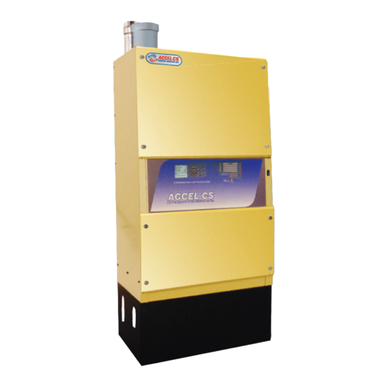
Accel CS
EK1C, EK2C, EK3C
INSTALLATION & SERVICE MANUAL
MANUFACTURED BY:
ENERGY KINETICS, INC.
51 Molasses Hill Road
Lebanon, NJ 08833
(908) 735-2066
www.energykinetics.com
This product meets the
®
Energy Star
guidelines
for efficiency.
Accel CS Boiler - Gas Heat - Eighth Edition – January, 2015
™
Accel CS features
Removable panels
for easy internal
access
National
Board Listed
ASME certified by EKI.
Certificate plate is on the
front center of the vessel.
Advertisement
Table of Contents


Need help?
Do you have a question about the EK2C and is the answer not in the manual?
Questions and answers