ENERGY KINETICS EK-1 Manual
Gas commercial boiler
Hide thumbs
Also See for EK-1:
- Owners and installation manual (26 pages) ,
- Installation & service manual (38 pages) ,
- Instructions manual (19 pages)
Table of Contents
Advertisement
Quick Links
MH27877
ANSI Z21.13-2014
Low-Press Boiler
INSTALLER:
PLEASE HANG THIS INSTRUCTION MANUAL AND ACCESSORY
INSTRUCTIONS VISIBLY NEXT TO THE BOILER USING THE
SUPPLIED POUCH.
OWNER:
PLEASE RETAIN THIS INSTRUCTION MANUAL AND ACCESSORY
INSTRUCTIONS FOR FUTURE REFERENCE.
Gas Commercial Boiler
Manufactured By:
Energy Kinetics, Inc.
51 Molasses Hill Road
Lebanon, NJ 08833
(908) 735-2066
www.energykinetics.com
Fourth Edition August 2022
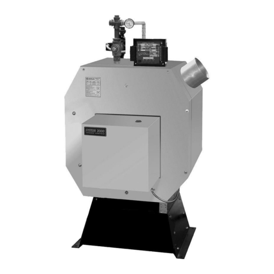
EK3 Frontier
ASME certified by
EKI. Certificate plate
is under the jacket on
the steel vessel.
National
Board Listed
Advertisement
Table of Contents

Subscribe to Our Youtube Channel
Related Manuals for ENERGY KINETICS EK-1


Summary of Contents for ENERGY KINETICS EK-1
- Page 1 EK3 Frontier Gas Commercial Boiler Manufactured By: Energy Kinetics, Inc. 51 Molasses Hill Road National Lebanon, NJ 08833 Board Listed MH27877 (908) 735-2066 ASME certified by ANSI Z21.13-2014 www.energykinetics.com EKI. Certificate plate Low-Press Boiler is under the jacket on the steel vessel.
-
Page 2: Please Read This First
Please Read This First Special Attention Flags Please pay particular attention to the following flags when you see them throughout this manual. DANGER: Notifies you of hazards that WILL cause severe personal injury, death or substantial property damage. WARNING: Notifies you of hazards that CAN cause severe personal injury, death or substantial property damage. CAUTION: Notifies you of hazards that WILL or CAN cause minor personal injury or property damage. -
Page 3: General Care And Maintenance
WARNING: Have the burner/boiler started up and serviced at least once annually by a qualified service technician. Professional care is necessary to properly service your equipment and verify it is operating reliably. Failure to properly maintain the equipment could result in severe personal injury, death or substantial property damage. -
Page 4: For Your Safety Read Before Operating
FOR YOUR SAFETY READ BEFORE OPERATING If you do not follow these instructions exactly, a fire or explosion WARNING: may result causing property damage, personal injury or loss of life. This burner does not have a pilot. It is Use only your hand to turn the gas supply equipped with an ignition device which ball valve. -
Page 5: Record Of Installation
DATE INSTALLED: NOTES: This manual covers the Energy Kinetics System 2000 EK3 Frontier Boiler. The boiler is designed and equipped and has been tested to generate hot water in a low pressure closed loop system. The boiler is a major component of a closed loop system that can be used as a heat source for hydronic heating, hydronic air handler, radiant, domestic hot water, spa, and/or pool heating systems. -
Page 6: Table Of Contents
TABLE OF CONTENTS PLEASE READ THIS FIRST ................................... 1 GENERAL CARE AND MAINTENANCE ..............................2 FOR YOUR SAFETY READ BEFORE OPERATING ..........................3 WHAT TO DO IF YOU SMELL GAS ............................... 3 OPERATING INSTRUCTIONS ................................3 TO TURN OFF GAS TO THE BURNER..............................3 RECORD OF INSTALLATION ................................ -
Page 7: Ek3 Frontier Gas Heat Boiler - Commercial - Residential
EK3 FRONTIER GAS HEAT BOILER - COMMERCIAL - RESIDENTIAL IMPORTANT MESSAGE: These instructions should be carefully read and kept for future reference to gain the best performance from your System 2000 Frontier boiler. CONGRATULATIONS ON THE PURCHASE OF a SYSTEM 2000 BOILER with its highly efficient low mass hydronic heat exchanger, the Energy Converter. -
Page 8: Principle Of Operation - System 2000 Boilers
PRINCIPLE OF OPERATION - SYSTEM 2000 BOILERS SYSTEM 2000 comprises a heat source, the energy converter, circulating water, and five (or more) zones controlled by an electronic control, the Energy manager. The Boiler sits cold until a thermostat calls for heat. The Energy manager receives the call for heat and turns on the bypass circulator and burner. -
Page 9: Receiving And Unpacking
stage is usually set at twenty minutes for space heating zones and is fixed at five minutes for the Hot Water zone. (See Energy manager Option Switch Settings). RECEIVING and UNPACKING Inspect shipment upon receipt for external damage. When unpacking and uncrating, inspect each item for internal damage. -
Page 10: Chimney Venting
Alternatively, a flexible metal vent connector may be used between the flue collar of the boiler and a flexible metal liner. Call Energy Kinetics for details on metal liners. Chimney connectors should be positioned to create the shortest possible run of flue pipe to the chimney. The overall horizontal length of flue piping should not exceed 15 feet. - Page 11 SYSTEM 2000 Boilers. Call Energy Kinetics for help locating sources of L-Vent. 1. L-Vent must be U.L. Listed to U.L. 641.
-
Page 12: Gas Burner Mounting
NOTICE: Gas burners should be installed according to burner manufacturer instructions, according to installation instructions below, and with consultation from Energy Kinetics for any special considerations or adjustments. To install burner, start by checking electrode and flame sense rod position per manufacturer’s specifications prior to assembly to unit. -
Page 13: Aquastat Settings
Capacities in Cubic Feet per Hour for Black Iron Pipe Carrying Natural Gas or Propane NATURAL GAS PROPANE Total Length of Gas Piping from Meter to Total Length of Gas Piping from Meter to Burner Burner Connection (Feet) Connection (Feet) Pipe Size Pipe Size (inches) -
Page 14: Boiler Mounting
TSP is recommended for removing flux and other oil based compounds. Once system has been cleaned and flushed, then add antifreeze to obtain approximately a 30% by volume mixture of antifreeze in water. Call Energy Kinetics for assistance in calculating how much anti-freeze to add to system. -
Page 15: Piping And Wiring Diagrams
Emergency Switch turned off. To have the service outlet controlled by the System Emergency Switch, move the service outlet black lead to top lug of system switch. A manual reset low water cut-off is factory installed by Energy Kinetics, either... -
Page 16: Prepare For Start Up
PREPARE FOR START UP DANGER: MAKE CERTAIN THE FOLLOWING REQUIREMENTS HAVE BEEN SATISFIED BEFORE START UP: 1. The boiler and piping are completely filled with water. 2. Re-check wiring to ensure that it is correct and in accordance with appropriate wiring diagrams and codes. 3. -
Page 17: Gas Burner Operation
GAS BURNER OPERATION NOTICE: For reliable operation, set Air-Fuel mixture conservatively based on installation conditions. Carbon dioxide, Oxygen, and Carbon Monoxide readings should be taken through 1/4" test port in front jacket opening just to right of burner (see FIG. 5A). Sample tube must extend at least six (6) inches into front cover to obtain accurate readings. - Page 18 Energy Manager Use the Energy Manager control with one or more zones directly off the boiler is needed and benefit from the Energy Manager energy recovery cycle, such as for large load with multiple zones (5 10 & 15 zone versions of the Energy Manager are available), primary/secondary injection (5 10 & 15 zone ERC Controls are available) with multiple boilers, or as a dedicated hot water maker.
- Page 19 24VAC output from all transformers. The Energy Manager is designed to heat domestic water and up to four (4) heating zones. Use Energy Kinetics supplied zone valves with four wire connections. For more than four heating zones, use Energy Kinetics expanded 10 or 15 zone Energy Manager, or call Energy Kinetics for alternatives.
-
Page 20: Install Energy Manager
INSTALL ENERGY MANAGER The Energy Manager is shipped in its own protective shipping box. NOTICE: The option switches can be set very easily before the Manager is installed. Locate the pre-wired quick connectors fastened to the front of the junction box by two cable ties. - Page 21 Dip Switch Settings Set dip switches for Fuel type: Oil or Gas and Vent type: Chimney or Inducer INSTALLATION TIPS Dip Switches “OFF” Display Managers are shipped with both dip switches “OFF” (set for an oil system with a chimney). ...
-
Page 22: Expanded Energy Manager
EXPANDED ENERGY MANAGER 15 Zone Manager Figure 4C Loop Circ Relay Loop Circ Connected to 11 ONE OUTPUTS ONE INPUTS 24V AC (THERMOSTA TS) ( ONE V AL VES O R ONE CIRC RELA YS) ONE 14 ONE 14 ONE 13 ONE 13 ONE 12 ONE 12... -
Page 23: Energy Manager Operation
Energy Manager Operation WARNING: Do Not Jump! If you apply 24VAC to any Energy sensor lead with the sensor connected to the Manager, you will burn out both the sensor and the Manager in less than a second. NOTE: The Manager cannot lockout the primary control on the burner. -
Page 24: 2-Minute Energy Manager Diagnostic
Energy Manager Check Troubleshooting The burner will not run unless there is a call for heat (thermostat call) or a call for domestic hot water (tank aquastat). Note: Do NOT Jumper Connections or Apply Voltage to Test the Manager. Follow these simple steps: Look at the Manager See what it is telling you is supposed to be happening. - Page 25 1, 2, and 3. If problem persists, call technical support or replace manager. Note malfunction on warranty tag and return manager to Energy Kinetics. If problem goes away, there is a problem with the output wiring – check all wiring, re-connect quick-connector and repeat steps 1, 2 and 3 until problem is resolved.
-
Page 26: Additional Manager Tests
Additional Manager Tests Perform the following tests ONLY if you have any of the following: Case 1) Zones heating intermittently Case 2) E140 or E150 displayed WITHOUT a burner lockout Case 3) E100 or E190 displayed If you have a burner lockout, troubleshoot as any conventional burner lockout. Case 1: Zones heating intermittently Step 1: Have all connected thermostats including hot water aquastat call continuously for at least 10 minutes. -
Page 27: Display Manager Return Sensor (Thermistor) Testing
Display Manager Return Sensor (Thermistor) Testing The temperature sensor in the return line allows better boiler control, and virtually eliminates condensation caused by cold returns. The temperature sensor is a thermistor sealed with epoxy inside a stainless steel well. The thermistor communicates continuously with the Manager thousands of times a minute. -
Page 28: Troubleshooting With The Energy Manager
TROUBLESHOOTING with the ENERGY MANAGER Display Manager Error Codes and Faults An error code on the display indicates that Display Manager has detected a problem. E100: Temperature sensor is not working properly. This indicates that the Manager is in service board mode. Circulator and inducer run constantly, burner runs off the high limit aquastat. -
Page 29: Operation Without The Energy Manager
F and zone will get heat on call. IF A PLUG-IN RELAY FAILS: Replace with spare relay. If spare is not available, temporarily install a relay with 24VAC coil and 120VAC contacts. Contact Energy Kinetics for connection details. EMERGENCY HEAT WITHOUT ENERGY MANAGER or RELAY BOARD (Temporary Operation Only –... - Page 30 EK3 Frontier Boiler Manual, Gas Edition August 2022...
-
Page 31: Annual Maintenance
ANNUAL MAINTENANCE Summary: Each year an efficiency check is recommended as part of basic maintenance. It is recommended that CO, , stack temperature, draft at the breech and draft over fire be checked. A draft loss through boiler of .0 ” to .10” w.c. is normal. -
Page 32: Replacement Parts
The flame former is of high quality refractory ceramic fiber material and will normally not need to be replaced. A replacement, if required, is available from Energy Kinetics. Ensure that the burner head is protected by the amulet, wet pack or a similar material. -
Page 33: Sys-08-024 Ek3 Gas With Digital Manager
SYS-08-024 EK3 Gas with Digital Manager ENERG MANAGER ORANGE GREEN 24 A H T E O AD B UE T hermisto r or Dig ital Sen sor ( ocate in Bo iler Retu rn ip ing ) S NG E RE F ROM 1 OUT UT T O 24 AUX 120 A O ER N... -
Page 34: Sys-08-019 Ek2 With Zone Cir And Dhw
SYS-08-019 EK2 with Zone Cir and DHW EK3 Frontier Boiler Manual, Gas Edition August 2022... -
Page 35: Sys-08-020 Ek3 With Heat,Dhw & Injection
OUTLET SYS-08-020 EK3 with Heat,DHW & Injection EK3 Frontier Boiler Manual, Gas Edition August 2022... - Page 36 T E M P . S E N S . EK3 Frontier Boiler Manual, Gas Edition August 2022...
- Page 37 TEM P. SENS. EK3 Frontier Boiler Manual, Gas Edition August 2022...
- Page 38 TEM P. SENS. EK3 Frontier Boiler Manual, Gas Edition August 2022...
- Page 39 T E M P . S E N S . EK3 Frontier Boiler Manual, Gas Edition August 2022...
- Page 40 T E M P . S E N S . EK3 Frontier Boiler Manual, Gas Edition August 2022...
- Page 41 EK3 Frontier Boiler Manual, Gas Edition August 2022...
-
Page 42: Sys-02-023 Large Dhw Storage Volume
SYS-02-023 Large DHW Storage Volume EK3 Frontier Boiler Manual, Gas Edition August 2022... - Page 43 OUT ET EK3 Frontier Boiler Manual, Gas Edition August 2022...
- Page 44 TEM . SENS. EK3 Frontier Boiler Manual, Gas Edition August 2022...
- Page 45 EK3 Frontier Boiler Manual, Gas Edition August 2022...
- Page 46 EK3 Frontier Boiler Manual, Gas Edition August 2022...
- Page 47 T EM P. SENS. EK3 Frontier Boiler Manual, Gas Edition August 2022...
- Page 48 EK3 Frontier Boiler Manual, Gas Edition August 2022...
-
Page 49: Sys-04-019 Multiple Ek3 Boiler Intallation
SYS-04-019 Multiple EK3 Boiler Intallation note 7 EK3 Frontier Boiler Manual, Gas Edition August 2022... - Page 50 EK3 Frontier Boiler Manual, Gas Edition August 2022...
- Page 51 EK3 Frontier Boiler Manual, Gas Edition August 2022...
- Page 52 EK3 Frontier Boiler Manual, Gas Edition August 2022...
-
Page 53: Common Flue Pipe Sizing
Common Flue Pipe Sizing See Note 1 See Note 1 EK-3 EK-3 12" Dia or 12"x16" 14" Dia or 12"x16" EK-3 EK-3 Two Boiler Flue Pipe Sizing EK-3 See Note 1 Three Boiler Flue Pipe Sizing EK-3 12" 16"Dia See Note 1 EK-3 18"Dia 16"x16"... - Page 54 ENERGY KINETICS SYSTEM 2000 SPECIFICATIONS EK 3 FRONTIER BOILER 4 Slot " 40" 1/2" 7/8" " 15" 12" Notes: 1. With Burner, Air Frame and High Limit Aquastat removed, bo iler " 25" depth is 32". 50" See Note 1...
- Page 55 2'-6" 6'-2" 2'-6" 2'-6" 2'-8" 11'-2" 6'-1" 5'-9" 1'-10 " 1'-4 " EK3 Frontier Boiler Manual, Gas Edition August 2022...
-
Page 56: Limited Warranty
Energy Kinetics is notified of the defect as follows: 2nd year - 30%, 3rd year - 40%, 4th year - 50%, and 5th year - 60%. - Page 57 Phone: 800-323-2066 Fax: 800-735-2068 EK3 Frontier Boiler Manual, Gas Edition August 2022...
Need help?
Do you have a question about the EK-1 and is the answer not in the manual?
Questions and answers