Table of Contents
Advertisement
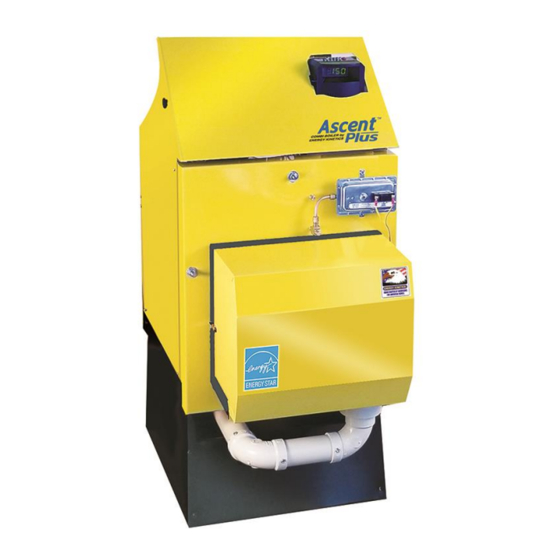
For Polypropylene Venting
Energy Kinetics is an ENERGY
®
STAR
Partner and a leading
manufacturer of ENERGY
®
STAR
heating equipment.
.
MH28303
UL 726;
Low-Press Boiler
INSTALLER:
Ascent Oil – August 2019
Ascent™ Combi and
Ascent™ Plus Combi
Model EK1T & EK1T+ Oil Fired
OWNER AND INSTALLATION MANUAL
Energy Kinetics, Inc.
51 Molasses Hill Road
www.energykinetics.com
HANG THIS INSTRUCTION MANUAL AND ACCESSORY INSTRUCTIONS VISIBLY NEXT
TO THE BOILER USING THE SUPPLIED POUCH.
Boilers
Manufactured By:
Lebanon, NJ 08833
(908) 735-2066
1
For Conventional Venting
National Board
Listed
ASME certified by EKI.
Certificate plate is under
the jacket on the steel
vessel.
Advertisement
Table of Contents

Related Manuals for ENERGY KINETICS SYSTEM 2000 Ascent Combi


Summary of Contents for ENERGY KINETICS SYSTEM 2000 Ascent Combi
- Page 1 For Polypropylene Venting For Conventional Venting Ascent™ Combi and Ascent™ Plus Combi National Board Boilers Energy Kinetics is an ENERGY Listed ® STAR Partner and a leading manufacturer of ENERGY ® STAR heating equipment. Model EK1T & EK1T+ Oil Fired...
- Page 2 HOMEOWNER/USER: READ AND SAVE THIS INSTRUCTION MANUAL AND ACCESSORY INSTRUCTIONS FOR FUTURE REFERENCE. PLEASE READ THIS FIRST Special Attention Flags Please pay particular attention to the following flags when you see them throughout this manual. DANGER: Notifies you of hazards that WILL cause severe personal injury, death or substantial property damage. WARNING: Notifies you of hazards that CAN cause severe personal injury, death or substantial property damage.
- Page 3 Homeowner/User: General care and maintenance of your boiler: Please read through the information provided for you in this manual. Ask your qualified service technician to explain normal operation of your equipment. Daily inspect the space around the burner/boiler to verify the area is clean and free of the materials listed above. Monthly watch the operation of your burner/boiler through an operating cycle to verify normal operation.
-
Page 4: Table Of Contents
TABLE of CONTENTS TABLE of CONTENTS ................................4 HOMEOWNER/USER NOTE: ..............................5 RECORD OF INSTALLATION ..............................6 SCOPE ...................................... 6 INSTALLER NOTE: .................................. 7 ASCENT COMBI and ASCENT PLUS COMBI BOILER ......................8 PRINCIPLE OF OPERATION ..............................8 RECEIVING and UNPACKING ..............................9 LOCATION and CLEARANCE .............................. -
Page 5: Homeowner/User Note
HOMEOWNER/USER NOTE: EMERGENCY SHUT DOWN INSTRUCTIONS: Turn power off to boiler by switching the “Oil Burner Emergency Switch” (typically located at the top of basement stairway or at boiler room entrance) to the OFF position. Shut off oil supply valve. NOTICE Do not use this boiler if any part has been under water. -
Page 6: Record Of Installation
SCOPE This manual covers the Energy Kinetics Ascent Combi Boiler. The boiler is designed and equipped and has been tested to generate hot water in a low pressure closed loop system. The boiler is a major component of a closed loop system that can be used as a heat source for hydronic, radiant, domestic hot water, spa, and/or pool heating systems. -
Page 7: Installer Note
INSTALLER NOTE: ALL INSTALLATIONS MUST BE MADE IN ACCORDANCE WITH ALL NATIONAL, STATE AND LOCAL, PLUMBING, HEATING AND ELECTRICAL CODES THAT MAY DIFFER FROM THIS MANUAL AND IN ACCORDANCE WITH THE FOLLOWING CODES, AS APPLICABLE: N.F.P.A. No. 70: National Electrical Code A.N.S.I. / N.F.P.A. No. 211: Chimneys, Fireplaces, Vents and Solid Fuel Burning Appliances A.N.S.I. -
Page 8: Ascent Combi And Ascent Plus Combi Boiler
The Boiler maintains a minimum temperature (in stock configuration, see “advanced settings”) until a heating zone or zone controller (supplied by Energy Kinetics or sourced locally) signals a call for heat, or the domestic water flow switch signals hot water flow in excess of about ½ GPM. The Ascent Hydrostat control receives the call for heat or hot water and turns on the heat and/or hot water/bypass circulators, and turns on the burner if the boiler is not hot enough to satisfy the demand. -
Page 9: Receiving And Unpacking
RECEIVING and UNPACKING Inspect shipment upon receipt for external damage. Walk TIP: around the freight and identify and address any unusual signs of handling with the shipper before signing for the delivery. This is a fast and easy way to resolve all transportation damage claims. When unpacking and uncrating, inspect each item for internal damage. -
Page 10: Combustion Air
Installations should utilize the Energy Kinetics boiler stand or a suitable solid, stable, level, and smooth foundation for the boiler. If not using an Energy Kinetics supplied stand, provide a solid, level, and smooth foundation with clearance for door opening and service. Place the unit as near to the chimney or vent as possible allowing clearance for front cleaning and service as shown in Figure 1A and 1B. -
Page 11: Conventional Chimney Venting - Ascent Combi Only
5”diameter for EK1T Ascent Combi (a 6” diameter chimney liner may be required at 1.25 GPH firing rate). Energy Kinetics has 5” flexible metal chimney connectors available to be used between the boiler flue collar and the chimney. -
Page 12: L-Vent Chimney - Ascent Combi Only
If a minimum of -0.02” w.c. draft at the breech is not present after sufficient burner run time to heat up the chimney, there is a problem that will need to be corrected. Call Energy Kinetics for help resolving draft problems. Under normal circumstances, there is NO need for a DRAFT REGULATOR and one should not be installed. -
Page 13: Oil Burner Settings
Ascent Combi and Ascent Plus Combi Boilers are shipped from the factory with the oil burner pre-mounted. The burner flanges are designed to insert the burner head 2-3/8” into the boiler. Energy Kinetics installs a ceramic sleeve, (the amulet), to protect the burner head from the heat of combustion, and then seals the air tube flange joint with a high-grade retort cement. -
Page 14: General Assembly
Assembly of various packaged units is illustrated in figure 2A and 2B as well as throughout this manual. The use of non- Energy Kinetics supplied pump, controls and accessories should follow good practices. The diagrams and locations presented in the manual are recommended. - Page 15 FIGURE 2B – BOILER FEED and EXPANSION TANK LOCATION ITEMS INSIDE PHANTOM BOX NOT INCLUDED WITH SYSTEM OPTIONAL TRIM KIT INCLUDES: EXP TANK & FEEDER/PREVENTER OPTIONAL PREMIER KIT INCLUDES: FEEDER/PREVENTER FEEDWATER CONNECTION EXPANSION TANK TO BE LOCATED IN RETURN PIPING FIGURE 2B Ascent Oil –...
- Page 16 Supply and return connections are 1”NPT on the EK1T Ascent Combi and EK1T+ Ascent Plus Combi. Call Energy Kinetics to obtain piping and wiring instructions for alternate applications, such as hydronic heating, radiant heating, domestic hot water, swimming pool heating, multiple boilers, injection loops, etc.
-
Page 17: Zone Control
Figure 2D Zoning with Circulators ZONE CONTROL ZONE CONTROL BY VALVE: Heating zones controlled by zone valves will require a separate power supply for the valve(s) with end switch(s) to complete the call for heat to the Ascent Hydrostat control. A multi zone valve panel (EK P/N: 10-1216, ZVC404 or equivalent) may also be used;... -
Page 18: Boiler Bypass Circulator
ZONE PURGING: Valves to isolate and purge individual zones should be installed according to good piping practices. EXPANSION TANK SIZING: The type and size of expansion tank depends on the total system water volume. The EK1T Ascent Combi and the EK1T+ Ascent Plus Combi contain 3 gallons of water. NOTICE: Sizing must consider cold start and hot operation due to system concepts of cold start and rapid heat up. -
Page 19: Boiler Water Treatment
(where allowed by local regulations). Once system has been cleaned and flushed, then add antifreeze to obtain approximately a 30% by volume mixture of antifreeze in water. Call Energy Kinetics for assistance in calculating how much anti-freeze to add to system. -
Page 20: Line Voltage Wiring Diagrams
LINE VOLTAGE WIRING DIAGRAMS Figure 3A Combi All wiring installations in: The United States must comply with the NEC, and any local codes. Ascent Oil – August 2019... -
Page 21: Wiring And Controls
WARNING: Make All Connections with Power Off at Main Circuit Box A typical low voltage wiring diagram for the Energy Kinetics Ascent Combi and Ascent Plus Combi is shown in the “Zone Control” section of this manual. Thermostats must be located on inside walls away from cold drafts, windows or heat from fireplaces, appliances or sunlight. -
Page 22: Advanced Settings
ADVANCED SETTINGS To improve efficiency, the EK1T Ascent Combi and the EK1T+ Ascent Plus Combi boilers have been equipped with advanced features designed to reduce idle loss (the energy required to keep the boiler in standby mode). Option 1 (OP1) – Maintain Temperature – Good Efficiency, Best Hot Water Convenience Option 2 (OP2) –... -
Page 23: Emergency Wiring
Remove this jumper to set the proper limit setting. When replacing the temporary Universal Hydrostat with the Energy Kinetics Ascent Hydrostat, follow the wiring instructions found in the Line Voltage Wiring Diagram section of this manual. Ascent Oil – August 2019... -
Page 24: Troubleshooting The Safety Pressure Switches (Ascent Plus Only)
TROUBLESHOOTING THE SAFETY PRESSURE SWITCHES (ASCENT PLUS ONLY) In addition to the blocked vent (puff) switch present on all Ascent boilers, the Ascent Plus has two additional pressure switches and a stack temperature limit switch to ensure safe operation in the event of several possible failure conditions. The blocked vent switch measures the over fire pressure to ensure the boiler maintains negative pressure in the boiler before the Dilution Air Exhaust Fan (inducer). -
Page 25: Prepare For Start Up
PREPARE FOR START UP DANGER: MAKE CERTAIN THE FOLLOWING REQUIREMENTS HAVE BEEN SATISFIED BEFORE START UP: 1. The boiler and piping are completely filled with water and purged of air. 2. Re-check wiring to ensure that it is correct and in accordance with appropriate wiring diagrams and codes. 3. -
Page 26: Oil Burner Operation
OIL BURNER OPERATION NOTICE: For reliable operation, set Air-Fuel mixture conservatively based on installation conditions. CO draft readings should be taken through the over fire test port in front jacket opening at right of burner (see FIG. 6). A 1/4" O.D. -
Page 27: Annual Tune Up & Inspection
ANNUAL TUNE UP & INSPECTION Step 1 Initial Test (Draft Check & CO Flue Box If there is an optional Silent Burner Cover, make sure it is in place before testing 1. Remove the 1/8” brass plug from the flue box plug (1) in the top right corner of the front cover. - Page 28 Step 6 Remove Drawer Assembly 1. Check Electrode Setting. 2. Check Porcelain Condition. 3. Check Nozzle for coking/heat. 4. Replace nozzle if necessary. See installation manual for nozzle selection. ANNUAL TUNE UP & INSPECTION Step 7 Check Burner 1. Check end cone through air tube opening with drawer assembly removed. 2.
- Page 29 Step 9 Plate Heat Exchanger Maintenance 1. Close the isolating ball valve located on the bypass circ flange, connect a drain hose to the hydronic bypass wye strainer, open flush valve, and flush into a bucket to remove debris. Close flush valve, remove drain hose, open isolating ball valve on bypass circ flange, and confirm boiler pressure is adequate, adding makeup water if necessary.
- Page 30 Step 10 Start Burner & Check Safety Functions. Smoke Check & Record: test 1. Draft must be negative at flue box port (1). Ascent Combi Chimney: Draft at the breech should be slightly negative (at least -.02”wc). Ascent Plus Combi: Draft at the breech should be negative (at least -.10”wc, although it may be substantially higher depending on the vent system).
-
Page 31: Hot Water Maintanence
Energy Kinetics recommends using a citric acid descaler such as Hercules HAYMAKER™ for the following reasons: 1. Chemical compatibility with all components and gaskets. -
Page 32: Replacement Parts
REPLACEMENT PARTS Obtain replacement parts from your local Energy Kinetics dealer. Contact Energy Kinetics at 800-323-2066 or www.energykinetics.com for help locating your nearest authorized dealer. EK1T EK1T ITEM DESCRIPTION ITEM DESCRIPTION PART NO. PART NO. Rear Insulation Board 2” 10-0828... - Page 33 NOTES: Ascent Oil – August 2019...
- Page 34 Ascent Oil – August 2019...
- Page 35 Model EK1T or Model EK1T+, is free from defects in material and workmanship for three years from the date of installation. If any parts are found to be defective in manufacture, Energy Kinetics will repair or replace the defective parts.
- Page 36 If within 30 days of the discovery, this action does not produce a prompt response, notify Energy Kinetics, Inc. 51 Molasses Hill Road, Lebanon, NJ 08833, in writing with details to support the warranty claim.
Need help?
Do you have a question about the SYSTEM 2000 Ascent Combi and is the answer not in the manual?
Questions and answers