Table of Contents
Advertisement
.
MH28303
UL 726;
CAN/CSA-B140.7-05
CAN/CSA-B140.0-03
CAN/CSA-B139-M91
Low-Press Boiler
INSTALLER:
HANG THIS INSTRUCTION MANUAL AND ACCESSORY INSTRUCTIONS VISIBLY NEXT
TO THE BOILER USING THE SUPPLIED POUCH.
HOMEOWNER/USER: READ AND SAVE THIS INSTRUCTION MANUAL AND ACCESSORY INSTRUCTIONS FOR
FUTURE REFERENCE.
This product meets the Energy Star
guidelines for efficiency
Frontier Boilers
OWNER AND INSTALLATION MANUAL
OILHEAT EDITION
Manufactured By:
Energy Kinetics, Inc.
51 Molasses Hill Road
Lebanon, NJ 08833
(908) 735-2066
www.energykinetics.com
EIGHTEENTH EDITION – JUNE 2015
®
®
®
ASME certified by EKI.
Certificate plate is under
the jacket on the steel
vessel.
Advertisement
Table of Contents

Related Manuals for ENERGY KINETICS System 2000 EK1 Frontier


Summary of Contents for ENERGY KINETICS System 2000 EK1 Frontier
- Page 1 This product meets the Energy Star guidelines for efficiency Frontier Boilers ® OWNER AND INSTALLATION MANUAL OILHEAT EDITION Manufactured By: MH28303 Energy Kinetics, Inc. UL 726; ASME certified by EKI. CAN/CSA-B140.7-05 Certificate plate is under 51 Molasses Hill Road CAN/CSA-B140.0-03 the jacket on the steel...
-
Page 2: Please Read This First
Please Read This First… Special Attention Flags Please pay particular attention to the following flags when you see them throughout this manual. DANGER: Notifies you of hazards that WILL cause severe personal injury, death or substantial property damage. WARNING: Notifies you of hazards that CAN cause severe personal injury, death or substantial property damage. CAUTION: Notifies you of hazards that WILL or CAN cause minor personal injury or property damage. -
Page 3: Table Of Contents
TABLE OF CONTENTS Page Topic Page Topic Please read this first Electrical Connection - Line Voltage Table of Contents Low Voltage Wiring and Diagram Homeowner/User Note Install Digital Manager Record of Installation Digital Manager Option Switch Settings SYSTEM 2000 Boiler - Principle of Operation Expanded Digital Manager Installation Digital Manager - Principle of Operation 12 Zone Manager Installation Instructions... -
Page 4: Homeowner/User Note
HOMEOWNER/USER NOTE: EMERGENCY SHUT DOWN INSTRUCTIONS: Turn power off to boiler by switching the “Oil Burner Emergency Switch” (typically located at the top of basement stairway or at boiler room entrance) to the OFF position. If unable to locate the “Oil Burner Emergency Switch” then switch the “System Emergency Switch”... -
Page 5: Record Of Installation
SCOPE This manual covers the Energy Kinetics System 2000 Frontier Boiler. The boiler is designed and equipped and has been tested to generate hot water in a low pressure closed loop system. The boiler is a major component of a closed loop system that can be used as a heat source for hydronic, radiant, domestic hot water, spa, and/or pool heating systems. -
Page 6: System 2000 Boiler - Principle Of Operation
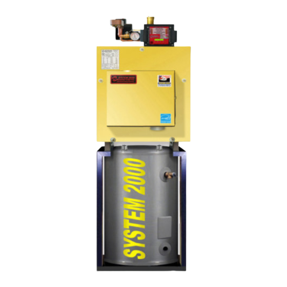
Your System 2000 holds a minimal quantity of water so it begins to supply heat in about 90 seconds. This rapid response means that your rooms can be heated quickly to temperature. The System 2000 EK1 Frontier can heat water up to 100,000 BTU’s per hour and the EK2 Frontier up to 200,000 BTU/hr. -
Page 7: Receiving And Unpacking
6. MONITOR RETURN TEMPERATURE: The Manager continually senses the return temperature and will turn off the zone outputs if the return temperature drops below 120 F (130 F if Option Switch #1 is ON). With the zone outputs closed, the boiler water will quickly reheat and once the return temperature reaches 140 F (150 F if Option Switch #1 is ON), then the Manager will reopen the zone valves. -
Page 8: Combustion Air
Place the unit as near to the chimney or vent as possible allowing clearance for front cleaning and service as shown in Figure 1B. If not using an Energy Kinetics supplied stand, provide a solid, level, and smooth foundation with clearance for door opening and service. -
Page 9: Chimney Venting
The metal liner diameter and length should be as recommended by the metal liner manufacturer. Corrugated metal liners should be at least 5" diameter for EK1 and 6" diameter for EK2. Energy Kinetics has 5” for EK1 and 6” for EK2 flexible metal chimney connectors available to be used between the boiler flue collar and the chimney. -
Page 10: Vent Chimney
It is recommended that Frontier systems be equipped with a (optional) fuel filter and a (optional) flexible fuel line. Call Energy Kinetics to obtain optional UL Listed fuel filter and optional UL Listed flexible fuel line. The flexible fuel line allows the door to open without disconnecting the fuel supply. -
Page 11: Oil Burner Settings
SYSTEM 2000 Boilers are shipped from the factory with the oil burner pre-mounted. The burner flanges are designed to insert the burner head 2-3/8” into the boiler. Energy Kinetics installs a ceramic sleeve, (the amulet), to protect the burner head from the heat of combustion, and then seals the air tube flange joint with a high grade retort cement. -
Page 12: General Assembly
GENERAL ASSEMBLY Assembly of various packaged units is illustrated throughout this manual. The use of non-Energy Kinetics supplied pump, controls and accessories should follow good practices. The diagrams and locations presented in the manual are recommended. BOILER MOUNTING BOILER MOUNTING on TANK STAND, FIG. 2A: Ensure that the boiler is properly mounted to the stand using the 5/16”... -
Page 13: Piping
ZONE CONTROL BY VALVE: The SYSTEM 2000 Boiler is designed to provide multi-zone control of the heating system and optionally can supply domestic hot water. Energy Kinetics recommends and supplies two wire, full port, 24-volt zone valves for control of each heating zone. A system with a single heating zone still requires a zone valve to provide control for preheat of unit and to maintain minimum temperature during operation. -
Page 14: Boiler Bypass Line And Valve
ZONE CONTROL BY CIRCULATOR: Zone control by circulators requires a flow valve, circulator and 24-volt relay (Multi relay kits or Individual relays such as a RIB relay available from Energy Kinetics) for each zone. The main circulator and boiler bypass line are still used in these cases. NOTICE: An additional tee must be installed into the supply on the inlet side of the main circulator. -
Page 15: Winterizing
Propylene Glycol in water will provide the following freeze protection: 30% down to +8F, 40% to -8F, 50% to -27F. Energy Kinetics recommends using 30% anti-freeze to obtain the best boiler performance. Use over 30% anti-freeze only if lower temperature freeze protection is mandatory. -
Page 16: Electrical Connection - Line Voltage
“B”. Be sure to verify 24VAC output from all transformers. The Digital Manager is designed to heat domestic water and up to four (4) heating zones. Use Energy Kinetics supplied zone valves with two wire connections. For more than four heating zones, use Energy Kinetics 12 zone expanded Digital Manager, or call Energy Kinetics for alternatives. -
Page 17: Digital Manager Option Switch Settings
DIGITAL MANAGER OPTION SWITCH SETTINGS ( Switches are located on bottom of Digital Manager) STANDARD MANAGER DIP SWITCHES EXPANDED MANAGER DIP SWITCHES Figure 4B 1 2 3 4 7 8 9 ZONE: 10 11 12 13 4 ALARM LEADS COMMON NORM. -
Page 18: Expanded Digital Manager Installation
EXPANDED DIGITAL MANAGER HEATING THERMOSTAT THERMOSTAT HEATING HOT WATER 24VAC INDUCER CHIMNEYLESS ONLY BURNER CIRCULATOR POWER CIRC CAUTION 24 VAC CONNECTION ONLY. READ INSTRUCTIONS BEFORE MAKING ANY CONNECTIONS MONITOR Legacy 10 and 15 Zone... -
Page 19: Security System Interface Wiring
The wiring detail is shown in Figure 5. NOTICE: Home security systems may require an “abort delay” of one second to avoid a transient signal on Manager power-up. If an abort delay is not available, use Energy Kinetics System Monitor (provided separately part # 10-0168). -
Page 20: Start Up Procedure
14. Punch a ¼” sampling hole in flue pipe as near to unit as possible in flue outlet for flue gas temperature and loosen 1/8” NPT hex plug in front jacket (to right of burner) for the over fire sampling location. CAUTION: All covers, enclosures, and guards must be maintained in place at all times, except during maintenance and servicing. -
Page 21: Oil Burner Operation
OIL BURNER OPERATION NOTICE: For reliable operation, set Air-Fuel mixture conservatively based on installation conditions. CO and draft readings should be taken through 1/4" test port in front jacket opening just to right of burner (see FIG. 6). Sample tube must extend at least eight (8) inches into front cover to obtain accurate readings. Smoke test and stack temperature should be taken at flue outlet. -
Page 22: Digital Manager Operation Summary
DIGITAL MANAGER OPERATION WARNING: Do Not Jump! If you apply 24VAC to any digital sensor lead with the sensor connected to the Manager, you will burn out both the sensor and the Manager in less than a second. NOTE: The Manager cannot lockout the primary control on the burner. -
Page 23: Digital Energy Manager Check
Digital Energy Manager Check Troubleshooting The burner will not run unless there is a call for heat (thermostat call) or a call for domestic hot water (tank aquastat). Note: Do NOT Jumper Connections or Apply Voltage to Test the Manager. Follow these simple steps: 1) Look at the Manager 2) See what it is telling you is supposed to be happening. -
Page 24: Additional Tests
(output) quick connector and repeat steps 1, 2, and 3. If problem persists, call technical support or replace manager. Note malfunction on warranty tag and return manager to Energy Kinetics. If problem goes away, there is a problem with the output wiring – check all wiring, re-connect quick connector and repeat steps 1, 2 and 3 until problem is resolved. -
Page 25: Digital Manager Sensor Testing
If resistance is greater than 3 ohms after 3 seconds of operation, B1-B2 contact is bad. Solution: Replace manager. Note: For 140F light flashing with a good B1-B2 manager relay (step 3 above), see “Trouble Shooting with the Digital Manager”. Digital Manager Sensor Testing The temperature sensor in the return line allows better boiler control, and virtually eliminates condensation caused by cold returns. -
Page 26: Troubleshooting With Digital Manager
TROUBLESHOOTING with the DIGITAL MANAGER Flashing Light indicates that Digital Manager has detected a problem. Monitor light comes on after a pre-determined period of time during which the system attempts to recover. New Digital Mangers 100/190°F lights flash if sensor is not working properly. ... -
Page 27: Operation Without The Digital Manager
F and zone will get heat on call. IF A PLUG-IN RELAY FAILS: Replace with spare relay. If spare is not available, temporarily install a relay with 24VAC coil and 120VAC contacts. Contact Energy Kinetics for connection details. Oil Heat – Eighteenth Edition – June 2015... -
Page 28: Diagnostics With The Digital Manager
DIAGNOSTICS with the DIGITAL MANAGER Manager Lights Temperature Description DIAGNOSIS Preheat cycle – zones will open when (1) Normal Operation boiler return is above 140 F (150 F if option switch 1 is on). Thermostat calling Return temperature dropped during ... -
Page 29: Annual Tune Up & Inspection
ANNUAL TUNE UP & INSPECTION Step 1 Initial Test (Draft Loss & CO Make sure air box cover is in place before testing 1. Remove 1/8” brass plug from the “over fire” test port (2) next to the burner and the flue box (1) next to the puff switch. - Page 30 ANNUAL TUNE UP & INSPECTION Step 7 Check Burner 1. Check end cone through air tube opening with drawer assembly removed. 2. Check Fan/Air Inlet for dirt or lint. 3. Install drawer assembly and check ignitor. 4. Check Filter condition. Replace annually or if vacuum exceeds 7” for single pipe systems.
-
Page 31: Replacement Parts
The combustion chamber is of high quality refractory ceramic fiber material and will normally not need to be replaced. A replacement chamber, if required, LOOSEN, BUT DO NOT REMOVE is available from Energy Kinetics. The proper part number for the Frontier NUTS, THE DOOR HINGES ON THESE BOLTS chamber must be specified when ordering. -
Page 32: Rear Cover
Replacement Parts Obtain replacement parts from your local Energy Kinetics dealer. Contact Energy Kinetics at 800-323-2066 or www.energykinetics.com for help locating your nearest authorized dealer. ITEM Frontier Frontier DESCRIPTION PART NO. PART NO. 10-0710 10-0810 Combustion Chamber 10-0394 10-0395 Energy Converter (Frontier) -
Page 33: Limited Lifetime Warranty
In the event that such pressure vessel is found to be defective in material or workmanship during the first ten years, Energy Kinetics will repair or replace the pressure vessel at its option and include a labor allowance per the published schedule. - Page 34 The End User is required to make available for inspection by Energy Kinetics or its representative, the parts claimed to be defective and, if requested by Energy Kinetics, to ship said parts prepaid to Energy Kinetics at the above address for inspection or repair. In addition, the homeowner agrees to make all reasonable efforts to settle any disagreement arising in connection with this claim before resorting to legal remedies in courts.
Need help?
Do you have a question about the System 2000 EK1 Frontier and is the answer not in the manual?
Questions and answers