Table of Contents
Advertisement
Quick Links
Installation and Assembly:
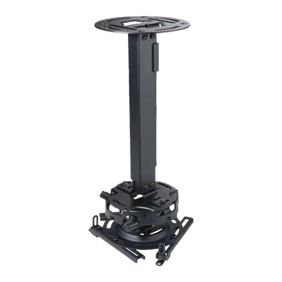
Projector Ceiling/Wall Mount
Model#
EXA, EXA-S, EXA-W, EXB, EXB-S,
EXB-W, EXC, EXC-S, EXC-W
Shown with PRG
projector mount and
projector (not included)
Features:
• For use with PRG-UNV and PRS-UNV Projector Mounts
• EXA and EXB series for ceiling or wall mounting
• EXC models for ceiling mounting
• Integrated cable management
• Various height adjustments for ideal viewing positions
Visit the Peerless Web Site at www.peerlessmounts.com
3215 W. North Ave. • Melrose Park, IL 60160 • (800) 865-2112 or (708) 865-8870 • Fax: (708) 865-2941 • www.peerlessmounts.com
Max UL Load Capacity
used with PRS projector mount
used with PRG projector mount
Installed to
Ceiling
1 of 11
R
Installed to Wall
(EXC models are not wall mountable
due to its extensive reach)
ISSUED: 1-11-08 SHEET #: 055-9495-2 10-16-08
For customer care call 1-800-865-2112 or 708-865-8870.
25 lb (11.3 kg)
50 lb (22.7 kg)
This product is intended for use with UL
Listed products and must be installed by a
qualified professional installer.
Shown with PRS
projector mount and
projector (not included)
Advertisement
Table of Contents

Related Manuals for PEERLESS EXA


Summary of Contents for PEERLESS EXA
-
Page 1: Installation And Assembly
Installation and Assembly: Projector Ceiling/Wall Mount Model# Max UL Load Capacity EXA, EXA-S, EXA-W, EXB, EXB-S, used with PRS projector mount 25 lb (11.3 kg) EXB-W, EXC, EXC-S, EXC-W used with PRG projector mount 50 lb (22.7 kg) This product is intended for use with UL Listed products and must be installed by a qualified professional installer. -
Page 2: Table Of Contents
Note: Read entire instruction sheet before you start installation and assembly. WARNING • Do not begin to install your Peerless product until you have read and understood the instructions and warnings contained in this Installation Sheet. If you have any questions regarding any of the instructions or warnings, please call Peerless customer care at 1-800-865-2112. -
Page 3: Parts List
Before you begin, make sure all parts shown are included with your product. Parts List EXA, EXA-S, EXA-W, EXB-S EXB-W EXC-S EXC-W Description Qty. Part # Part # Part # Part # Part # Part # ceiling plate 055-1773 055-4773 055-2773 055-1773 055-4773... -
Page 4: Install Outer Channel To Ceiling Plate
Part List Continued Parts may appear slightly different than illustrated. Install Outer Channel to Ceiling Plate Attach outer channel (B) to ceiling plate (A) using four M6 x 10 mm socket pin screws (L) as shown. Tighten screws with security wrench (P). 4 of 11 ISSUED: 1-11-08 SHEET #: 055-9495-2 10-16-08 Visit the Peerless Web Site at www.peerlessmounts.com... -
Page 5: Installation To Wood Joist Ceiling Or Wood Stud Wall
Installation to Wood Joist Ceilings or Wood Stud Walls WARNING • Installer must verify that the supporting surface will safely support the combined load of the equipment and all attached hardware and components. • Tighten wood screws so that ceiling/wall plate is firmly attached, but do not overtighten. Overtightening can damage the screws, greatly reducing their holding power. -
Page 6: Installation To Solid Concrete Ceiling Or Concrete/Cinder Block Walls
Installation to Concrete Ceilings or Concrete/Cinder Block Walls WARNING • When installing Peerless wall mounts on cinder block, verify that you have a minimum of 1-3/8" of actual concrete thickness in the hole to be used for the concrete anchors. Do not drill into mortar joints! Be sure to mount in a solid part of the block, generally 1"... -
Page 7: Installing Inner Channel And Routing Cables
Installing Inner Channel and Routing Cables Note: Be certain holes on inner channel (C) face in the same direction of opening on outer channel (B). Note: Cables must be removed from projector before routing through channels. If cables are not removable from projector, routing through channels is not an option. -
Page 8: Installing Projector Mount
Installing Projector Mount Installing PRG projector mount with ceiling installation: Attach vertical mounting plate (E) to PRG projector mount (not included) using two M5 x 16 mm socket pin screws (G), four flat washers (O) and two locknuts (N) as shown in figure 4.1. -
Page 9: Installing Projector
Installing Projector Mount (continued) Ceiling installation: Insert vertical mounting plate (E) into inner channel (C) with projector mount in the correct orientation shown in figure 5.1 or 5.2. Secure vertical mounting plate to inner channel using four socket pin screws (M) as shown in figure 5.3. CEILING INSTALLATION fig. -
Page 10: Adjusting Mount Extension
Adjusting Mount Extension While supporting the weight of the projector, loosen clamp plate screws half a turn and position projector to the desired extended position. Retighten clamp plate screws securely. WARNING • On ceiling installations, clamp plate adjustment screws support weight of projector when fully tightened. Weight of the projector will need to be supported if clamp plate screws are loosened. -
Page 11: Projector Alignment
ISSUED: 1-11-08 SHEET #: 055-9495-2 10-16-08 Visit the Peerless Web Site at www.peerlessmounts.com For customer care call 1-800-865-2112 or 708-865-8870. © 2008, Peerless Industries, Inc. All rights reserved. All other brand and product names are trademarks or registered trademarks of their respective owners.
Need help?
Do you have a question about the EXA and is the answer not in the manual?
Questions and answers