Advertisement
Available languages
Available languages
Quick Links
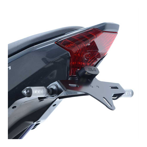
FITTING INSTRUCTIONS FOR LP0159BK LICENCE PLATE BRACKET
YAMAHA MT-07 '14-
THIS KIT CONTAINS THE ITEMS PICTURED AND LABELLED BELOW.
DO NOT PROCEED UNTIL YOU ARE SURE ALL PARTS ARE PRESENT.
Please note that the way the kit is packed does not necessarily represent the way of mounting to the bike.
T
(
)
HE PARTS SHOWN MAY BE REPRESENTATIVE ONLY
FOR CLARITY OF INSTRUCTIONS ONLY
6
7
8
9
5
5
10
4
11
3
12
13
2
1
14
15
R&G Racing
Unit 1, Shelley's Lane, East Worldham, Alton, Hampshire, GU34 3AQ
Tel: +44 (0)1420 89007 Fax: +44 (0)1420 87301
www.rg-racing.com
Email:
info@rg-racing.com
Advertisement

Subscribe to Our Youtube Channel
Related Manuals for R&G LP0159BK


Summary of Contents for R&G LP0159BK
- Page 1 FITTING INSTRUCTIONS FOR LP0159BK LICENCE PLATE BRACKET YAMAHA MT-07 ’14- THIS KIT CONTAINS THE ITEMS PICTURED AND LABELLED BELOW. DO NOT PROCEED UNTIL YOU ARE SURE ALL PARTS ARE PRESENT. Please note that the way the kit is packed does not necessarily represent the way of mounting to the bike.
-
Page 2: Tools Required
LEGEND ITEM 1 = LICENCE PLATE BRACKET (TB0159 Part 2) (x1). ITEM 2 = LA0002 No. PLATE LIGHT ASSEMBLY (x1). ITEM 3 = MAIN BRACKET (TB0159 Part 1) (x1). ITEM 4 = 150mm LENGTH OF HEATSHRINK (x3). ITEM 5 = M6 x 16mm LONG BUTTON HEAD BOLTS (x4). ITEM 6 = WIRING CONNECTORS (INDICATORS) (CON0027) (x2). - Page 3 Picture 1 Picture 2 Picture 3 Picture 4 Picture 5 Picture 6 R&G Racing Unit 1, Shelley’s Lane, East Worldham, Alton, Hampshire, GU34 3AQ Tel: +44 (0)1420 89007 Fax: +44 (0)1420 87301 www.rg-racing.com Email: info@rg-racing.com...
- Page 4 Picture 7 Picture 8 Picture 9 Picture 10 Picture 11 Picture 12 R&G Racing Unit 1, Shelley’s Lane, East Worldham, Alton, Hampshire, GU34 3AQ Tel: +44 (0)1420 89007 Fax: +44 (0)1420 87301 www.rg-racing.com Email: info@rg-racing.com...
- Page 5 Picture 13 Picture 14 Picture 15 Picture 16 Picture 17 Picture 18 R&G Racing Unit 1, Shelley’s Lane, East Worldham, Alton, Hampshire, GU34 3AQ Tel: +44 (0)1420 89007 Fax: +44 (0)1420 87301 www.rg-racing.com Email: info@rg-racing.com...
- Page 6 Picture 19 Picture 20 Picture 21 Picture 22 Picture 23 Picture 24 R&G Racing Unit 1, Shelley’s Lane, East Worldham, Alton, Hampshire, GU34 3AQ Tel: +44 (0)1420 89007 Fax: +44 (0)1420 87301 www.rg-racing.com Email: info@rg-racing.com...
- Page 7 Picture 25 Picture 26 Picture 27 Picture 28 Picture 29 Picture 30 R&G Racing Unit 1, Shelley’s Lane, East Worldham, Alton, Hampshire, GU34 3AQ Tel: +44 (0)1420 89007 Fax: +44 (0)1420 87301 www.rg-racing.com Email: info@rg-racing.com...
- Page 8 Picture 31 Picture 32 Picture 33 Picture 34 Picture 35 Picture 36 R&G Racing Unit 1, Shelley’s Lane, East Worldham, Alton, Hampshire, GU34 3AQ Tel: +44 (0)1420 89007 Fax: +44 (0)1420 87301 www.rg-racing.com Email: info@rg-racing.com...
-
Page 9: Fitting Instructions
Picture 37 Picture 38 Picture 39 Picture 40 FITTING INSTRUCTIONS To fit the R&G tail tidy, remove the pillion seat using the key and the rider’s seat by removing the two bolts under each corner of the seat, as shown in picture 1. ... - Page 10 On the underside of the panel, near the key lock on the left side, there is a small push rivet that also needs to be removed, as shown in picture 8. Do this on both sides of the bike. ...
- Page 11 Align the four holes and fit the four M6 x 16mm long button head bolts (item 5) through the main bracket and then the cover plate, as shown in picture 34. Offer the assembly up to the underside of the bike, feeding the wires through the large hole in the rear subframe, and loosely tighten the four M6 x 16mm long button head bolts (item 5) into the subframe mounts, as shown in picture 35.
- Page 12 INSTRUCTIONS DE MONTAGE POUR LP0159BK SUPPORT DE PLAQUE YAMAHA MT-07 ’14- Assurez vous que toutes les pièces soient présentes avant de procéder au montage. La façon dont le kit est emballé ne correspond pas forcément à la façon de monter les pieces sur la moto.
-
Page 13: Outils Requis
LEGENDE ARTICLE 1 = SUPPORT DE PLAQUE (TB0159 Part 2) (x1). ARTICLE 2 = LA0002 No. ASSEMBLAGE FEU DE PLAQUE(x1). ARTICLE 3 = SUPPORT PRINCIPAL (TB0159 Part 1) (x1). ARTICLE 4 = 150mm LONGUEUR THERMORETRACTABLE (x3). ARTICLE 5 = M6 x 16mm BOULONS (x4). ARTICLE 6 = CONNECTEURS DE FILS (CLIGNOTANTS) (CON0027) (x2). - Page 14 Photo 1 Photo 2 Photo 3 Photo 4 Photo 5 Photo 6 R&G Racing Unit 1, Shelley’s Lane, East Worldham, Alton, Hampshire, GU34 3AQ Tel: +44 (0)1420 89007 Fax: +44 (0)1420 87301 www.rg-racing.com Email: info@rg-racing.com...
- Page 15 Photo 7 Photo 8 Photo 9 Photo 10 Photo 11 Photo 12 R&G Racing Unit 1, Shelley’s Lane, East Worldham, Alton, Hampshire, GU34 3AQ Tel: +44 (0)1420 89007 Fax: +44 (0)1420 87301 www.rg-racing.com Email: info@rg-racing.com...
- Page 16 Photo 13 Photo 14 Photo 15 Photo 16 Photo 17 Photo 18 R&G Racing Unit 1, Shelley’s Lane, East Worldham, Alton, Hampshire, GU34 3AQ Tel: +44 (0)1420 89007 Fax: +44 (0)1420 87301 www.rg-racing.com Email: info@rg-racing.com...
- Page 17 Photo 19 Photo 20 Photo 21 Photo 22 Photo 23 Photo 24 R&G Racing Unit 1, Shelley’s Lane, East Worldham, Alton, Hampshire, GU34 3AQ Tel: +44 (0)1420 89007 Fax: +44 (0)1420 87301 www.rg-racing.com Email: info@rg-racing.com...
- Page 18 Photo 25 Photo 26 Photo 27 Photo 28 Photo 29 Photo 30 R&G Racing Unit 1, Shelley’s Lane, East Worldham, Alton, Hampshire, GU34 3AQ Tel: +44 (0)1420 89007 Fax: +44 (0)1420 87301 www.rg-racing.com Email: info@rg-racing.com...
- Page 19 Photo 31 Photo 32 Photo 33 Photo 34 Photo 35 Photo 36 R&G Racing Unit 1, Shelley’s Lane, East Worldham, Alton, Hampshire, GU34 3AQ Tel: +44 (0)1420 89007 Fax: +44 (0)1420 87301 www.rg-racing.com Email: info@rg-racing.com...
- Page 20 Photo 37 Photo 38 Photo 39 Photo 40 Instructions de montage: Pour monter le support de plaque, commencez par enlever le siège passager en utilisant une clé, puis le siège du pilote en enlevant les 2 boulons sous chaque coin du siège (photo 1).
- Page 21 Sur les caches de l’empennage, enlever le boulon 8mm et le boulon 4mm qui sont placés de chaque coté (Photo 7).Faire cela des 2 cotés de la moto. Sur la partie du dessous du cache, a coté l, près de la serrure à clé sur le côté gauche, il y a un petit rivet qui doit aussi être enlevé...
- Page 22 Prendre les plaques d’adaptateur de clignotant d’origine (Article 11 – I0037) et montez- en une à chaque caoutchouc de clignotant (photos 28 & 29). Placer les clignotants à travers le trou de support clignotant sur l’ensemble support de plaque (en plaçant le bon clignotant du bon coté...
- Page 23 Remettre la plaque d’immatriculation (peut nécessiter un perçage). Selon la loi locale, monter les réflecteurs (article 10) aux emplacements appropriés. Revérifiez que les clignotants et les feux de plaque fonctionnent bien avant de prendre la route. ISSUE 1 28/02/14 (AR) Ces instructions de montage sont disponibles au téléchargement sur www.rg-racing.com CONSUMER NOTICE...
- Page 24 MONTAGEANLEITUNG FÜR LP0159BK KENNZEICHENHALTER YAMAHA MT-07 ’14- ALLE TEILE SIND UNTEN ABGEBILDET UND GEKENNZEICHNET. BEVOR SIE MIT DER MONTAGE BEGINNEN, ÜBERPRÜFEN SIE, DASS ALLE TEILE VORHANDEN SIND. Hinweis: Die Verpackung der Teile stellt nicht die Reihenfolge der Montage dar. IE UNTEN ABGEBILDETEN EILE DIENEN LEDIGLICH ZUR RKLÄRUNG...
-
Page 25: Sie Benötigen Folgendes Werkzeug
LIEFERUMFANG: ARTIKEL 1 = KENNZEICHENHALTER (TB0159 Teil 2) (x1). ARTIKEL 2 = LA0002 KENNZEICHENBELEUCHTUNG (x1). ARTIKEL 3 = HALTERUNG (TB0159 Part 1) (x1). ARTIKEL 4 = 150mm SCHRUMPFSCHLAUCH (x3). ARTIKEL 5 = M6 x 16mm INBUSSCHRAUBEN (x4). ARTIKEL 6 = KABELVERBINDUNGEN (BLINKER) (CON0027) (x2). ARTIKEL 7 = ABDECKPLATTE (TB0159 Teil 2) (x1). - Page 26 Abbildung 1 Abbildung 2 Abbildung 3 Abbildung 4 Abbildung 5 Abbildung 6 R&G Racing Unit 1, Shelley’s Lane, East Worldham, Alton, Hampshire, GU34 3AQ Tel: +44 (0)1420 89007 Fax: +44 (0)1420 87301 www.rg-racing.com Email: info@rg-racing.com...
- Page 27 Abbildung 7 Abbildung 8 Abbildung 9 Abbildung 10 Abbildung 11 Abbildung 12 R&G Racing Unit 1, Shelley’s Lane, East Worldham, Alton, Hampshire, GU34 3AQ Tel: +44 (0)1420 89007 Fax: +44 (0)1420 87301 www.rg-racing.com Email: info@rg-racing.com...
- Page 28 Abbildung 13 Abbildung 14 Abbildung 15 Abbildung 16 Abbildung 17 Abbildung 18 R&G Racing Unit 1, Shelley’s Lane, East Worldham, Alton, Hampshire, GU34 3AQ Tel: +44 (0)1420 89007 Fax: +44 (0)1420 87301 www.rg-racing.com Email: info@rg-racing.com...
- Page 29 Abbildung 19 Abbildung 20 Abbildung 21 Abbildung 22 Abbildung 23 Abbildung 24 R&G Racing Unit 1, Shelley’s Lane, East Worldham, Alton, Hampshire, GU34 3AQ Tel: +44 (0)1420 89007 Fax: +44 (0)1420 87301 www.rg-racing.com Email: info@rg-racing.com...
- Page 30 Abbildung 25 Abbildung 26 Abbildung 27 Abbildung 28 Abbildung 29 Abbildung 30 R&G Racing Unit 1, Shelley’s Lane, East Worldham, Alton, Hampshire, GU34 3AQ Tel: +44 (0)1420 89007 Fax: +44 (0)1420 87301 www.rg-racing.com Email: info@rg-racing.com...
- Page 31 Abbildung 31 Abbildung 32 Abbildung 33 Abbildung 34 Abbildung 35 Abbildung 36 R&G Racing Unit 1, Shelley’s Lane, East Worldham, Alton, Hampshire, GU34 3AQ Tel: +44 (0)1420 89007 Fax: +44 (0)1420 87301 www.rg-racing.com Email: info@rg-racing.com...
- Page 32 Abbildung 37 Abbildung 38 Abbildung 39 Abbildung 40 MONTAGEANLEITUNG Um den R&G Kennzeichenhalter zu montieren, entfernen Sie den Beifahrersitz (Schlüssel benutzen), danach den Fahrersitz entfernen (entfernen Sie die zwei Schrauben unter jeder Ecke des Sitzes) – siehe Abbildung 1. ...
- Page 33 Auf der Unterseite der Verkleidung, in der Nähe des Schlüsselschlosses, ist eine kleine Befestigungsniete, die auch entfernt werden muss – siehe Abbildung 8. Diese Niete auch auf der anderen Seite des Motorrades entfernen. Das Heck und die Seitenverkleidungen können nun vorsichtig vom Motorrad entfernt werden – siehe Abbildungen 9 &...
- Page 34 Die Kabel können nun durch die zwei Öffnungen an jeder Seite des Halters geführt werden und mit den Kabelbindern und selbstklebenden Clips befestigt werden – siehe Abbildung 22 & 31. Nehmen Sie die Abdeckplatte (Artikel 7 – TB0159 Teil 3) und montieren Sie die Gummitülle (Artikel 8) in der mittleren Öffnung –...
Need help?
Do you have a question about the LP0159BK and is the answer not in the manual?
Questions and answers