Advertisement
Available languages
Available languages
Quick Links
LP0197
FITTING INSTRUCTIONS FOR LP0197BK LICENCE PLATE BRACKET
YAMAHA XSR900 '16-
Page | 1
THIS KIT CONTAINS THE ITEMS PICTURED AND LABELLED BELOW.
DO NOT PROCEED UNTIL YOU ARE SURE ALL PARTS ARE PRESENT.
Please note that the way the kit is packed does not necessarily represent the way of
mounting to the bike
T
(
)
HE PARTS SHOWN MAY BE REPRESENTATIVE ONLY
FOR CLARITY OF INSTRUCTIONS ONLY
13
14
15
16
17
18
19
20
R&G Racing
Unit 1, Shelley's Lane, East Worldham, Alton, Hampshire, GU34 3AQ
Tel: +44 (0)1420 89007 Fax: +44 (0)1420 87301
www.rg-racing.com
Email:
info@rg-racing.com
1
Advertisement

Related Manuals for R&G LP0197BK


Summary of Contents for R&G LP0197BK
- Page 1 LP0197 FITTING INSTRUCTIONS FOR LP0197BK LICENCE PLATE BRACKET YAMAHA XSR900 ’16- Page | 1 THIS KIT CONTAINS THE ITEMS PICTURED AND LABELLED BELOW. DO NOT PROCEED UNTIL YOU ARE SURE ALL PARTS ARE PRESENT. Please note that the way the kit is packed does not necessarily represent the way of...
-
Page 2: Tools Required
LP0197 LEGEND ITEM 1 = M6 x 16mm LONG BUTTON HEAD BOLTS (x4) ITEM 2 = M6 WASHERS (x8) ITEM 3 = SUB-FRAME (FOR ILLUSTRATION ONLY) ITEM 4 = LICENCE PLATE BRACKET (TB0197BK) (x1) Page | 2 ITEM 5 = M3 NUTS (x2). ITEM 6 = M3 WASHERS (x2). - Page 3 LP0197 Page | 3 PICTURE 3 PICTURE 4 PICTURE 5 PICTURE 6 PICTURE 7 PICTURE 8 R&G Racing Unit 1, Shelley’s Lane, East Worldham, Alton, Hampshire, GU34 3AQ Tel: +44 (0)1420 89007 Fax: +44 (0)1420 87301 www.rg-racing.com Email: info@rg-racing.com...
-
Page 4: Fitting Instructions
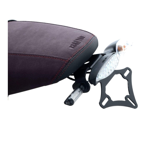
LP0197 Page | 4 PICTURE 9 PICTURE 10 PICTURE 11 PICTURE 12 FITTING INSTRUCTIONS Remove the seat using the key. Remove the four bolts that hold the seat lock mechanism (arrowed in picture 1) using 8mm socket and a wrench. ... - Page 5 LP0197 Fit the original indicator with the adapter to the new licence plate bracket (Item 4) and re- fit the spreader. Ensure that the adapter (Item 13) is sitting on the outside of the licence plate bracket (Item 4). ...
- Page 6 LP0197 Mount the licence plate bracket (Item 4) using the four M6 x 16mm (Item 1) with M6 washers (Item 2) through the top four holes on the sub-frame. Secure the assembly with M6 washer (Item 2) and M6 nyloc nut (Item 10) on each bolt as arrowed in picture 11. ...
- Page 7 LP0197 R&G shall at its option either supply a replacement or refund the purchase money but shall not be liable if the Products have been modified or used or maintained otherwise than in accordance with R&G’s or manufacturer’s instructions and good engineering practice or if the defect arises from accident or neglect.
- Page 8 LP0197 NOTICE DE MONTAGE POUR LP0197BK SUPPORT DE PLAQUE YAMAHA XSR900 ’16- Page | 8 Le kit contient les articles exposés ci-dessous, vérifier que toutes les pièces soient présentes avant de procéder au montage. A FAÇON DONT LE KIT EST EMBALLE NE CORRESPOND PAS FORCEMENT A LA FAÇON DE...
-
Page 9: Outils Requis
LP0197 LEGENDE Page | 9 ARTICLE 1 = M6 x 16mm BOULONS (x4) ARTICLE 2 = M6 RONDELLES (x8) ARTICLE 3 = SOUS CADRE (POUR ILLUSTRER UNIQUEMENT) ARTICLE 4 = SUPPORT DE PLAQUE (TB0197BK) (x1) ARTICLE 5 = M3 ECROUS (x2). ARTICLE 6 = M3 RONDELLES (x2). - Page 10 LP0197 Page | 10 PHOTO 3 PHOTO 4 PHOTO 5 PHOTO 6 PHOTO 7 PHOTO 8 R&G Racing Unit 1, Shelley’s Lane, East Worldham, Alton, Hampshire, GU34 3AQ Tel: +44 (0)1420 89007 Fax: +44 (0)1420 87301 www.rg-racing.com Email: info@rg-racing.com...
-
Page 11: Notice De Montage
LP0197 Page | 11 PHOTO 9 PHOTO 10 PHOTO 11 PHOTO 12 NOTICE DE MONTAGE Enlever le siège à l’aide de la clé. Enlever les 4 boulons qui fixent le mécanisme de blocage du siège (photo 1) avec une clé de 8mm. - Page 12 LP0197 Enlever le collier de serrage qui fixe la liasse de fils puis déclipser les 2 clips qui maintiennent les fils de clignotant sur l’unité de support de plaque d’origine (voir photo Si vous utilisez les clignotants d’origine : ...
- Page 13 LP0197 RESISTANCE NOIRE--------------------- NOIR (FEU DE PLAQUE) Prendre la rondelle caoutchouc 26mm du kit (Article 7) et placer la bague O (Article 9) fournie autour d’elle, voir photo 8. Presser doucement la rondelle de caoutchouc et insérez la dans le trou plus large sur le Page | 13 support de plaque (Article 4) voir photo 9.
- Page 14 LP0197 Vérifiez que les clignotants et les feux de plaque fonctionnent bien avant de prendre la route. Notice disponible au téléchargement sur www.rg-racing.com Page | 14 OUPLES DE SERRAGE RECOMMANDES M4 BOULON = 8Nm M5 BOULON = 12Nm M6 BOULON = 15Nm M8 BOULON = 20Nm M10 BOULON = 40Nm ISSUE 4 04/11/2016 (HH)
Need help?
Do you have a question about the LP0197BK and is the answer not in the manual?
Questions and answers