Table of Contents
Advertisement
Available languages
Available languages
Quick Links
LP0193
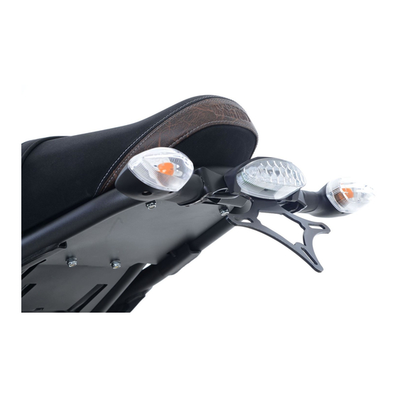
FITTING INSTRUCTIONS FOR LP0193BK LICENCE PLATE BRACKET
YAMAHA XSR700 '16-
Page | 1
THIS KIT CONTAINS THE ITEMS PICTURED AND LABELLED BELOW.
DO NOT PROCEED UNTIL YOU ARE SURE ALL PARTS ARE PRESENT.
Please note that the way the kit is packed does not necessarily represent the way of
mounting to the bike
T
(
)
HE PARTS SHOWN MAY BE REPRESENTATIVE ONLY
FOR CLARITY OF INSTRUCTIONS ONLY
13
14
15
16
17
18
R&G Racing
Unit 1, Shelley's Lane, East Worldham, Alton, Hampshire, GU34 3AQ
Tel: +44 (0)1420 89007 Fax: +44 (0)1420 87301
www.rg-racing.com
Email:
info@rg-racing.com
1
Advertisement
Table of Contents

Related Manuals for R&G LP0193BK


Summary of Contents for R&G LP0193BK
- Page 1 LP0193 FITTING INSTRUCTIONS FOR LP0193BK LICENCE PLATE BRACKET YAMAHA XSR700 ‘16- Page | 1 THIS KIT CONTAINS THE ITEMS PICTURED AND LABELLED BELOW. DO NOT PROCEED UNTIL YOU ARE SURE ALL PARTS ARE PRESENT. Please note that the way the kit is packed does not necessarily represent the way of...
-
Page 2: Tools Required
LP0193 LEGEND ITEM 1 = M6 x 50mm BUTTON HEAD BOLTS (x2) ITEM 2 = M6 x 15mm BUTTON HEAD BOLTS (x2) ITEM 3 = M6 WASHERS (16mm O/DIA) (x8) ITEM 4 = SPACER 35mm Long (S0795) (x2) ITEM 5 = SUB-FRAME (FOR ILLUSTRATION ONLY) Page | 2 ITEM 6 = COVER PLATE (TB0193 Pt.1) (x1) ITEM 7 = LICENCE PLATE BRACKET ASSEMBLY (TB0193 Pt.2) (x1) - Page 3 LP0193 Page | 3 PICTURE 3 PICTURE 4 PICTURE 5 PICTURE 6 PICTURE 7 PICTURE 8 R&G Racing Unit 1, Shelley’s Lane, East Worldham, Alton, Hampshire, GU34 3AQ Tel: +44 (0)1420 89007 Fax: +44 (0)1420 87301 www.rg-racing.com Email: info@rg-racing.com...
- Page 4 LP0193 Page | 4 PICTURE 9 PICTURE 10 PICTURE 11 PICTURE 12 PICTURE 13 PICTURE 14 R&G Racing Unit 1, Shelley’s Lane, East Worldham, Alton, Hampshire, GU34 3AQ Tel: +44 (0)1420 89007 Fax: +44 (0)1420 87301 www.rg-racing.com Email: info@rg-racing.com...
-
Page 5: Fitting Instructions
LP0193 Page | 5 PICTURE 15 PICTURE 16 PICTURE 17 FITTING INSTRUCTIONS Remove the seat using the key. Remove the four bolts that hold the seat catch as arrowed in picture 1 using 4mm Allen key. Remove the seat catch. ... - Page 6 LP0193 Remove the two nuts that hold the rear OEM tail light assembly (located on the bottom of the tail light unit) using 10mm socket and a ratchet. Remove the OEM tail light unit. Remove the 5 button head bolts that hold the rear mudguard (located on top of the mudguard) using 4mm Allen key.
- Page 7 LP0193 We suggest to cut the OEM male rear light connector approximately 50mm from the plug socket. Strip back the wires to allow male bullet connectors to be fitted. Fit and crimp the male connectors over each OEM wires (Yellow, Blue/Red and Black) ...
- Page 8 LP0193 Refit seat. Depending on local laws, attach enclosed red reflector (item 18) in an appropriate location. Please test the indicators, rear light, no. plate light and brake light before riding. Page | 8 GENERAL TORQUE SETTINGS M4 BOLT = 8Nm M5 BOLT = 12Nm M6 BOLT = 15Nm...
- Page 9 LP0193 NOTICE DE MONTAGE POUR LP0193BK SUPPORT DE PLAQUE YAMAHA XSR700 ‘16- Page | 9 Le kit contient les articles exposés ci-dessous, vérifier que toutes les pièces soient présentes avant de procéder au montage. A FAÇON DONT LE KIT EST EMBALLE NE CORRESPOND PAS FORCEMENT A LA FAÇON DE...
- Page 10 LP0193 Page | 10 LEGENDE ARTICLE 1 = M6 x 50mm BOULONS (x2) ARTICLE 2 = M6 x 15mm BOULONS (x2) ARTICLE 3 = M6 RONDELLES (16mm O/DIA) (x8) ARTICLE 4 = ENTRETOISE 35mm de long (S0795) (x2) ARTICLE 5 = SOUS CADRE (POUR ILLUSTRER UNIQUEMENT) ARTICLE 6 = PLAQUE DE COUVERTURE (TB0193 Pt.1) (x1) ARTICLE 7 = ASSEMBLAGE SUPPORT DE PLAQUE (TB0193 Pt.2) (x1) ARTICLE 8 = M6 ECROUS (x4)
-
Page 11: Outils Requis
LP0193 Notez que si les kits sont emballés avec des rondelles en caoutchouc servant à tenir les composants, ces rondelles doivent être jetées ! OUTILS REQUIS Clés Allen. Tournevis cruciforme Page | 11 Jeu de douilles. Pinces électriques / à... - Page 12 LP0193 d’origine à longueur adéquate, et pour sertir un connecteur mâle balle (article 13) sur les 2 fils. Sertir un connecteur femelle (Article 13) sur les 2 fils de clignotants R&G et joignez les 2 connections en connectant les connecteurs male et femelle ensemble. Brancher dans le faisceau pour vérifier le fonctionnement à...
-
Page 13: Couples De Serrage Recommandés
LP0193 Veiller à ce que le boulon passe bien par l’entretoise et que l’entretoise soit prise en sandwich entre le sous cadre le support de plaque (article 7). Fixer l’assemblage avec une rondelle M6 (Article 3) et un écrou M6 (Article 8). Répéter la procédure pour l’autre boulon M6 x 50mm (Article 1). - Page 14 LP0193 engineering practice or if the defect arises from accident or neglect. Other than identified above and subject to R&G not limiting its liability for causing death and personal injury, it shall not be liable for indirect or consequential loss and otherwise its liability shall be limited to the amounts paid by the Buyer for the Products or the fitting or service concerned.
Need help?
Do you have a question about the LP0193BK and is the answer not in the manual?
Questions and answers