
Related Manuals for Landoll 1230 Series


Summary of Contents for Landoll 1230 Series
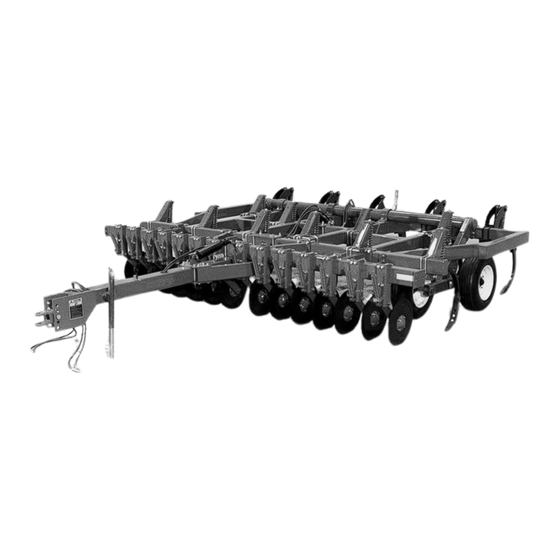
- Page 1 MODEL 1230 SERIES COULTER CHISEL OPERATOR’S MANUAL 1900 NORTH STREET MARYSVILLE, KANSAS 66508 (785) 562-5381 F-319-0501 05/01...
- Page 2 LANDOLL will not be liable for labor, transpor- tation, or any other charges resulting from replacement of a defective part. This warranty is void if any part not supplied by LANDOLL is used in assembly or repair, or if the machine has been altered, abused, or neglected.
- Page 3 MODEL 1230 SERIES COULTER CHISEL OPERATOR’S MANUAL PURCHASED FROM: DATE ADDRESS: PHONE NO.: SERIAL NO.:...
-
Page 4: Table Of Contents
TABLE OF CONTENTS SECTION DESCRIPTION PAGE NO. INTRODUCTION STANDARD SPECIFICATIONS ASSEMBLY INSTRUCTIONS ASSEMBLY - SAFETY ....... . . 3-1 AFTER ASSEMBLY - SAFETY . - Page 5 4-22 COULTER CUTTERS ....... . . 4-22 4-23 LEVELING BAR ........4-22 4-24 DEEP-TILL SHANKS .
- Page 6 SAFETY PRECAUTIONS THIS IS THE SAFETY ALERT SYMBOL. IT IS USED TO ALERT YOU TO POTENTIAL INJURY HAZARDS. OBEY ALL SAFETY MESSAGES THAT FOLLOW THIS SYMBOL TO AVOID POSSIBLE INJURY OR DEATH. DANGER DANGER INDICATES AN IMMINENTLY HAZARDOUS SITUA- TION WHICH, IF NOT AVOIDED, WILL RESULT IN DEATH OR SERIOUS INJURY.
-
Page 7: Introduction
INTRODUCTION The Landoll 1230 Series Coulter Chisel is a quality product designed to give years of trouble free per- formance. By following each section of this manual, your system will perform as designed for you and your operation. SECTION 1 gives basic instructions on the use of this manual. -
Page 9: Standard Specifications
STANDARD SPECIFICATIONS MODEL TYPE WORKING NO. OF NO. OF TRANS. TRANS. SHANKS CUTTERS WIDTH HEIGHT WIDTH FOLD TOTAL/REAR 7’-0” 9’-8” 6’-3” 12317 Rigid 8’-7” 9’-8” 6’-3” 12337 Rigid 9’-0” 9’-8” 6’-3” 12319 Rigid 11’-1” 9/5* 10’-9” 6’-3” 12339 Rigid 11’-0” 11/3 10’-9”... - Page 10 LANDOLL CORPORATION GENERAL TORQUE SPECIFICATIONS (REV. 4/97) THIS CHART PROVIDES TIGHTENING TORQUES FOR GENERAL PURPOSE APPLICATIONS WHEN SPECIAL TORQUES ARE NOT SPECIFIED ON PROCESS OR DRAWING. ASSEMBLY TORQUES APPLY TO PLATED NUTS AND CAPSCREWS ASSEMBLED WITHOUT SUPPLEMENTAL LUBRICATION (AS RECEIVED CONDITION).
- Page 11 LANDOLL CORPORATION HYDRAULIC FITTING TORQUE SPECIFICATIONS JIC, ORS, & ORB (REV. 10/97) THIS CHART PROVIDES TIGHTENING TORQUES FOR HYDRAULIC FITTING APPLICATIONS WHEN SPECIAL TORQUES ARE NOT SPECIFIED ON PROCESS OR DRAWING. ASSEMBLY TORQUES APPLY TO PLATED CARBON STEEL AND STAINLESS STEEL FITTINGS ASSEMBLED WITHOUT SUPPLEMENTAL LUBRICATION (AS RECEIVED CONDITION).
- Page 12 NOTES:...
-
Page 13: Assembly Instructions
ASSEMBLY INSTRUCTIONS 3-1 ASSEMBLY - SAFETY CAUTION It is very important that your new 1230 Series Coulter Chisel be properly assembled, adjusted and lubricated before use. Illustrations in this sec- 1. THE PERSON OR PERSONS WHO tion show proper assembly procedures. Remove ASSEMBLE THIS MACHINE MUST paint from grease fittings. - Page 14 WARNING WARNING 1. USE LIFT CRANE, JACK, TACKLE 1. WEAR PERSONAL PROTECTIVE OR FORK LIFT TRUCK TO LIFT HEAVY EQUIPMENT (PPE) SUCH AS, BUT NOT PARTS AND ASSEMBLIES. LIMITED TO, PROTECTION FOR EYES, LUNGS, EARS, HEAD, HANDS AND 2. KEEP CLEAR OF PARTS WHICH FEET WHEN OPERATING, SERVICING MAY MOVE OR DROP WHEN REMOV- OR REPAIRING EQUIPMENT.
-
Page 15: After Assembly - Safety
3-2 AFTER ASSEMBLY - SAFETY CAUTION WARNING BEFORE OPERATING THE MACHINE, 1 . B E S U RE ALL NUTS , BO LT S , BE SURE TO READ THE SAFETY AND OTHER FASTENERS AND HYDRAULIC OPERATION SECTIONS OF THE OP- FITTINGS ARE PROPERLY TIGHT- ERATOR’S MANUAL. -
Page 16: Main Frame And Hitch
3-4 MAIN FRAME AND HITCH 3-4.1 Place main frame on suitable stands at least 30" (76 cm) high. 3-4.2 Determine center of main frame and insert hitch tube under frame (See Figure 3-2). 3-4.3 Attach front of hitch tube to frame with mounting plates and four 3/4"... -
Page 17: Main Frame Rockshaft
3-5 MAIN FRAME ROCKSHAFT 3-5.1 Lay rockshaft (See Figure 3-5) on frame with wheel spindle holes in rockshaft lift arm toward front of frame. 3-5.2 Lubricate inside of rockshaft bearings and upper reinforcement bar surfaces. Notes: 10’-10” frame requires four bearings: Two inner and two outer. -
Page 18: Single Wheels
Figure 3-6 - Wheel Spindle and Adapter Figure 3-7 - Single Wheel Installation 3-6 SINGLE WHEELS 3-6.3 Insert spindle and adapter into lift arm, 3-6.1 Slide tube adapter (2-1/4" dia. x 7-1/2" align holes and install 3/8" x 3-1/2" cap long) over hub spindle (See Figure 3-6). -
Page 19: Lockup And Lift Cylinder
3-8 LOCKUP AND LIFT CYLINDER 3-8.3 Attach base end of frame lift hydraulic cyl- 3-8.1 Install lockup hook with 1" diameter. L-pin inder to frame cylinder anchor. and clip pin (See Figure 3-10). Lift Cylinder Sizes: 3-8.2 Install lift cylinder linkage arm with 3/4" x - All Rigid and 19’... -
Page 20: Cutter Frame And Cutters
Figure 3-14 Pivoting Support Bracket for Cutter Frame 3-10 CUTTER FRAME AND CUTTERS 3-10.1 Attach pivoting support brackets on main 3-10.3 Install disc cutter supports (See Figure frame front bar with 3/4" x 5-5/8" U-bolts, 3-16): lock washers and nuts (See Figures 3-14, - RH cutter supports (hubs toward right side 3-15, &... -
Page 21: Shovels
3-11 SHOVELS 3-11.1 Install shovels on shanks with two 1/2" plow bolts (See Figure 3-17). a. If installing 5-hole twisted shovels, use 2nd and 3rd holes with one hole below end of shank. b. If installing 3-hole shovels, use lower two holes with no holes below end of shank. -
Page 22: Wing Hinges
3-13 WING HINGES Install four folding wing hinges on front and rear bars of the main frame, both sides. 3-13.1 Attach each hinge to end of main frame with four 5/8" x 1-3/4" cap screws, lock- washers and nuts. Install one U-bolt main frame (See Figure 3-20). -
Page 23: Wing Rockshafts - 21' & 23' Models
3-16 WING ROCKSHAFTS - 21’ & 23’ MODELS 3-16.1 Install wing rockshafts and bearings using 3-16.2 Attach wheel to wing rockshaft with 3/8" x same procedure as installing main frame 2-1/2" cap screw, but without adapter (See rockshaft (See Section 3-5). Install one rein- (Figure 3-7). -
Page 24: Gauge Wheels
3-18 GAUGE WHEELS 3-18.4 Insert wheel support between plates. Use 3-18.1 Locate gauge wheels on outer end of cut- L-pin and clip pin to hold in place. ter wing frames as shown in assembly lay- 3-18.5 Install wheel on hub.Tighten wheel bolts to out. -
Page 25: Hydraulic System Assembly
3-19 HYDRAULIC SYSTEM ASSEMBLY IMPORTANT REFER TO THE TORQUE CHARTS TABLES 2-1 AND 2-2 FOR IMPORTANT INFORMATION ON THE TIGHTENING OF STRAIGHT-THREAD HY- DRAULIC FITTINGS. DO NOT USE PIPE SEALANT OR TEFLONÓ TAPE ON THREADS. DO NOT CONNECT ROD ENDS OF HY- DRAULIC CYLINDERS UNTIL AFTER THE HYDRAULIC SYSTEM IS PURGED OF AIR (SEE SECTION 3-19.4). - Page 26 Figure 3-31 - Selector Valve Location Figure 3-32 - Check Valve Diagram d. Install all remaining hydraulic cylinders, 3-19.3 Folding Models hoses and fittings shown on next page. a. Attach valve bracket to wing cylinder anchor tube with 1/2" U-bolt (See Figure 3-31). Notes: b.
- Page 27 Figure 3-35 - Front of RH Wing Figure 3-34 - Rear of RH Wing 3-19.4 Purging Air From Hydraulic System - Initial e. Thread wing lift cylinder hoses and cutter Assembly frame lift cylinder hoses through vertical hose supports during assembly (See Figures 3-34 IMPORTANT! and 3-35).
- Page 28 Figure 3-36 Main Frame Hydraulic Lift Circuit - 21’ & 23’ Folding Models Figure 3-37 Wing and Cutter Frame Hydraulic Lift Circuits - Folding Models 3-16...
- Page 29 Figure 3-38 9’-6” Main Frame Assembly Layout - Single Axle, 12” Shank Spacing Figure 3-39 9’-6” Main Frame Assembly Layout - Walking Beam Axle, 12” Shank Spacing 3-17...
- Page 30 Figure 3-40 9’-6” Main Frame Assembly Layout - Single Axle, 15” Shank Spacing Figure 3-41 9’-6” Main Frame Assembly Layout - Walking Beam Axle, 15” Shank Spacing 3-18...
- Page 31 Figure 3-42 10’-10” Main Frame Assembly Layout - Walking Beam Axle, 12” Shank Spacing 3-19...
- Page 32 Figure 3-43 10’-10” Main Frame Assembly Layout - Walking Beam Axle, 15” Shank Spacing 3-20...
- Page 33 Figure 3-44 10’-10” Main Frame Assembly Layout - 19’ Folding Model 3-21...
- Page 34 Figure 3-45 10’-10” Main Frame Assembly Layout - 21’ and 23’ Folding Models 3-22...
- Page 35 3-20 ELECTRICAL INSTALLATION 3-20.1 Assemble right and left hand warning 3-20.2 Install the assembled lights on the outside lights to the warning light brackets using of the frame just forward of the rear hinge 1/4-20 x 1-1/4 hex head cap screws and hex using bar and 1/2-13 x 5-1/2 hex head cap lock nuts.
- Page 36 NOTES: 3-24...
-
Page 37: Operation And Maintenance
OPERATION AND MAINTENANCE CAUTION The Model 1230 Series Coulter Chisel is a highly versatile primary tillage tool, adaptable to spring or fall tillage operations. Rigid-frame models 1. AVOID INJURY OR FATAL ACCI- are available in cutting widths from 7’ to 18 ’... - Page 38 WARNING CAUTION 1. DO NOT CLEAN, ADJUST OR SERV- 1. WEAR PERSONAL PROTECTIVE ICE WHEN THE MACHINE IS IN MO- EQUIPMENT (PPE) SUCH AS, BUT NOT TION. LIMITED TO, PROTECTION FOR EYES, LUNGS, EARS, HEAD, HANDS AND 2. ALL HYDRAULICALLY OR ME- FEET WHEN OPERATING, SERVICING CHANICALLY ELEVATED COMPO- OR REPAIRING EQUIPMENT.
- Page 39 CAUTION CAUTION 1. COMPLY WITH YOUR STATE AND 1. UTILIZE TRANSPORT CHAINS. THE LOCAL LAWS GOVERNING HIGHWAY TRANSPORT CHAIN SHOULD BE AD- SAFETY, LIGHTING & MARKING, AND JUSTED SO THAT THE TONGUE OF THE MOVEMENT OF FARM MACHIN- THE TOWED MACHINE WILL NOT ERY ON PUBLIC ROADS.
- Page 40 WARNING DANGER 1. BE CERTAIN THE HYDRAULIC SYS- 1. CLEAR THE AREA OF BYSTANDERS TEM IS FULLY CHARGED WITH OIL BEFORE STARTING OPERATION. BEFORE USE. AIR IN THE HYDRAULIC SYSTEM CAN RESULT IN UNCON- 2. STAY CLEAR OF THE FOLDING TROLLED MOVEMENT OF THE WINGS WINGS WHEN THEY ARE BEING DURING RAISING AND LOWERING OP-...
-
Page 41: Decals
4-1 DECALS a. Keep decals clean by wiping off regularly. 4-1.1 The following decals are installed to alert Use a cleaning solution if necessary. operators to hazards in specific machine ar- b. Replace missing, damaged or painted over eas. The decals are for personal safety... decals. -
Page 42: Rockshaft Lockup Operation
4-2 ROCKSHAFT LOCKUP OPERATION To install lockup: a. Raise implement to full height. b. Remove lockup from storage position and attach lockup to frame (See Figure 4-5). c. Insert lockup pin and install clip pin. d. Attach lockup to rockshaft in storage posi- tion when not in use (See Figure 4-6). -
Page 43: Tractor Preparation
4-3 TRACTOR PREPARATION WARNING 4-3.1 Prior to attaching the implement the tractor should be prepared as follows: a. Check fluid level in the tractor hydraulic sys- DO NOT UNHITCH FROM TRACTOR tem reservoir. Additional fluid may be re- WHILE IN THE RAISED POSITION. quired after charging the chisel plow hydraulic UNHITCHING THE MACHINE IN A circuits (See Section 4-38.7). -
Page 44: Attaching To Tractor
4-5 ATTACHING TO TRACTOR Note: Relieve internal hydraulic system pres- 4-5.1 Hitch sure before leaving tractor seat. The implement is equipped with a combination a. Hitch tractor to implement with a 1" (25 mm) clevis / tongue swivel hitch. For a tongue-type trac- pin (minimum diameter). -
Page 45: Purging The Hydraulic System
4-5.2 Transport Safety Chain d. Connect chain hook and secure with latch. a. Attach transport safety chain to chisel plow WARNING hitch with 1" x 8 " bolt furnished with machine bundle. Tighten bolt securely (See Figure 4-10). ALWAYS USE TRANSPORT SAFETY b. -
Page 46: Unhitching From Tractor
4-7 UNHITCHING FROM TRACTOR WARNING 4-7.1 Chisel Lowered IMPORTANT TO AVOID SERIOUS INJURY OR TO PREVENT CHISEL POINT DAMAGE, DO DEATH, STOP TRACTOR ENGINE, NOT LOWER CHISEL ON CONCRETE OR SHIFT TO PARK POSITION OR SHIFT ROCKS. TO NEUTRAL AND SET BRAKES BE- a. -
Page 47: Folding And Unfolding Wings
4-8 FOLDING AND UNFOLDING WINGS 4-8.1 To fold or unfold the wings on folding mod- els, turn the selector valve to “WING FOLD” position. WARNING TO AVOID SERIOUS INJURY OR DEATH, STOP TRACTOR ENGINE, DIS- ENGAGE PTO, SHIFT TO PARK POSI- TION OR SHIFT TO NEUTRAL SET BRAKES BEFORE LEAVING TRACTOR. -
Page 48: Lift Cylinder Operation (Folding Models)
4-10 LIFT CYLINDER OPERATION (FOLDING MODELS) 4-10.1 The master lift cylinder and wing slave cyl- inders should extend and retract equally to maintain the same depth. To ensure equal stroke length, occasionally hold the tractor depth control lever in raise position for a few seconds after raising the implement. -
Page 49: Measuring Crop Residue (Line-Transect Method)
4-13 MEASURING CROP RESIDUE (LINE-TRANSECT METHOD) Use the following procedure to determine the percentage of residue on the field. 4-13.1 Select a measuring tool: a. 100’ tape b. 100’ rope or string marked at 1’ intervals c. 50’ tape d. 50’ rope or string marked at 6" intervals 4-13.2 Stretch measuring tool (tape/rope/string) diagonally (30°... -
Page 50: Leveling The Chisel Plow
4-14 LEVELING THE CHISEL PLOW 4-14.1 All Models a. With the rockshaft lockup in storage posi- tion, drive the tractor forward and lower the implement into the ground. When the chisels are at the approximate desired depth, check that the frame is level and the chisels are at a uniform depth. -
Page 51: Gauge Wheels
4-15 GAUGE WHEELS 4-15.1 Folding Models The gauge wheels provide implement stability for the larger models. With the implement fully lowered, position the wheels to just touch the ground: a. Use gauge wheel adjustment lever (both sides), to raise wheels same distance above ground level as desired chisel working depth (See Figure 3-27). -
Page 52: Disc Cutters
4-16 DISC CUTTERS 4-16.1 For optimum performance, each disc cutter should be in line with one of the shanks, ex- cept the center shank. If necessary, adjust the disc cutter spacing on the frame to ob- tain correct alignment. 4-16.2 Disc cutter spring tension is increased or decreased by turning the adjuster nut at the top of each spring. -
Page 53: General Maintenance
4-19 GENERAL MAINTENANCE 4-19.1 Beginning Of Day 4-19.3 Beginning of Season a. Perform daily lubrication. a. Perform end-of-season lubrication. b. Check and adjust tire pressure: b. Check and adjust tire pressure. 9.5 L-15, 6-ply; 36 psi (250 kPa) c. Tighten all loose bolts, U-bolts and L-bolts. c. -
Page 54: Lubrication
4-20 LUBRICATION 4-20.1 Lubricate the implement according to Ta- a. Clean paint and dirt from all grease fittings ble 4-1. Be sure to: before attaching grease gun. b. Replace broken or missing fittings. Fig.* Item Grease 8 Hours 40 Hr. 200 Hr. - Page 55 Figure 4-28 Rockshaft Figure 4-29 Walking Beams Figure 4-30 Wheels Figure 4-31 Disc Cutters 4-19...
-
Page 56: Bolt Torque Checking Intervals
4-21 BOLT TORQUE CHECKING INTERVALS Figure 4-32 Disc Cutter Figure 4-33 Spring Cushion Clamp DISC CUTTER First First First Beginning Periodically TORQUE CHECK 8 Hr. 40 Hr. 250 Hr. of Season Pivot Bolt Bevel Nut U-Bolts SPRING CUSHION First First First Beginning Periodically... -
Page 57: Coulter Cutters
4-22 COULTER CUTTERS 4-22.1 Cutters with 22" diameter concave discs are standard equipment. The discs cut ag- gressively and mix residue with worked soil. 4-22.2 Rippled disc coulters 20" in diameter are available for loosely working the soil with minimal surface residue loss (See Figure 4-34). -
Page 58: Depth Control System
4-25 DEPTH CONTROL SYSTEM 4-25.1 The DCS 3000 Depth Control System al- lows automatic or manual depth control of towed implements (See Figure 4-37). An op- erator’s and installation instruction manual is included with the system bundle. Figure 4-37 Depth Control System Console 4-26 POINTS FOR SHANKS Note: Install an equal number of right and left 4-26.1 Two types of points are available for the... -
Page 59: Rear Bar Shank Extensions
4-27 REAR BAR SHANK EXTENSIONS 4-27.1 Extensions move standard or deep-till shanks on the rear bar 10" rearward for im- proving material flow in high-residue condi- tions (See Figure 4-40). Figure 4-40 Rear Bar Shank Extension 4-23... - Page 60 NOTES 4-24...
-
Page 61: Troubleshooting Guide
TROUBLESHOOTING GUIDE The Troubleshooting Guide, shown below, is included to help you quickly locate problems that can hap- pen using your 1230 Coulter Chisel. Follow all safety precautions stated in the previous when making any adjustments to your machine. PROBLEM PROBABLE CAUSE:SOLUTION 1. - Page 62 NOTES:...
- Page 64 Equipment from Landoll Corporation is built to exacting standards ensured by ISO 9001 registration at all Landoll manufacturing facilities. Model 1230 Series Coulter Chisel Operator’s Manual Re-Order Part Number F-319-0501 LANDOLL CORPORATION 1900 North Street Marysville, Kansas 66508 (785) 562-5381 800-428-5655 ~ WWW.LANDOLL.COM...
Need help?
Do you have a question about the 1230 Series and is the answer not in the manual?
Questions and answers