
Subscribe to Our Youtube Channel
Related Manuals for Infortrend EonNAS Pro 500 Series


Summary of Contents for Infortrend EonNAS Pro 500 Series
- Page 1 Infortrend Hardware Manual EonNAS Pro 500 / 800 Series EonNAS SE LEC T EonNAS_Pro_800 EN T ER EonNAS SELE CT EonNAS_Pro_500 EN TE R Version 1.1...
-
Page 2: Copyright Notice
Infortrend Technology, Inc. Disclaimer... -
Page 3: Safety Precautions
The use of Infortrend certified components is strongly recommended to ensure compatibility, quality and normal operation with your Infortrend products. Please contact your distributor for a list of Infortrend certified components (eg. SFP, SFP+, HBA card, iSCSI cable, FC cable, memory module, etc.). -
Page 4: Esd Precautions
ESD Precautions ESD Precautions Avoid touching the PCB boards or connector pins on the hard drives. Avoid dust, debris, carpets, plastic, vinyl, and styrofoam in your work area. Do not remove the hard disk drive from its anti-static bag before installation takes place. Hard drives must not be stacked on top of each other without their protective drive trays. -
Page 5: Service And Maintenance
Service and Maintenance Service and Maintenance Keep the faulty hard disk drive in place until you have a replacement unit in hand; removing a hard disk drive tray will affect airflow within the enclosure. When transporting the enclosure, repackage all disk drives separately in the original package foam blocks. -
Page 6: Table Of Contents
Table of Contents Table of Contents Copyright Notice....................2 Safety Precautions......................3 Important Notice ....................... 3 ESD Precautions ....................... 4 Service and Maintenance....................5 About This Manual....................8 Revision History........................ 8 Introduction ....................9 Front Panel Overview ..................10 Front panel......................11 Rear panel of EonNAS Pro 500 / 800 .............. - Page 7 Table of Contents Maintenance ..................... 46 Replacing the Hard Drive..................46 System Error Buzzer.................... 48 Restore Default Settings..................51 Appendix....................52 Technical Specifications..................52 6.1.1 Hardware ..................... 52 6.1.2 Operating Environment ................. 53 6.1.3 Host Port Pinouts..................53 6.1.4 1Gbps Ethernet Host Port / 1Gbps iSCSI Host Port........54 Certifications .......................
-
Page 8: About This Manual
About This Manual About This Manual This manual introduces the hardware components of EonNAS Pro NAS systems and describe how to install, operate and maintain them. The EonNAS Pro 800 will be use for front panel illustration purposes. Where necessary, EonNAS Pro 500 illustrations will be used to indicate differences. -
Page 9: Introduction
EonNAS Pro 500 / 800 Hardware Manual 1 Introduction The EonNAS Pro series of Network Attached Storage systems are high-performance and versatile storage solutions for sharing files and volumes across the Ethernet network. Network Attached Storage (NAS) separates application servers and data, and stores data on storage devices that perform dedicated file serving tasks. -
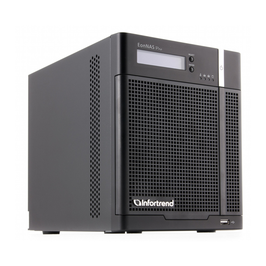
Page 10: Front Panel Overview
EonNAS Pro 500 / 800 Hardware Manual 1.1 Front Panel Overview The EonNAS Pro 500 and 800 are ruggedly built and come with five (5) and eight (8) hard drive bays for the latter two, respectively. The hard drive bay supports a single 3.5 inch SATA hard drive up to 3TB in storage capacity. -
Page 11: Front Panel
EonNAS Pro 500 / 800 Hardware Manual 1.2 Front panel Open the front panel, the EonNAS Pro 3 3 3 3 3 3 3 3 3 3 3 3 3 3 3 3 3 3 3 3 500 has 5 hard drive slots while the 3 3 3 3 3 3 3 3 3 3 3 3... -
Page 12: Rear Panel Of Eonnas Pro 500 / 800
EonNAS Pro 500 / 800 Hardware Manual 1.3 Rear panel of EonNAS Pro 500 / 800 There user serviceable components on the back of EonNAS Pro 500 / 800. From top to bottom, there is the power socket (1), eSATA port (2), USB ports (3), Ethernet port 1 (4), Ethernet port 2 (5), restore default button (6), VGA port (7) and... -
Page 13: Hard Drive Designation
EonNAS Pro 500 / 800 Hardware Manual 1.4 Hard Drive Designation The hard drives are placed in numeric order from top to bottom for EonNAS Pro 500 and 800. When installing hard drives, always start installing to the top empty tray and work your way down to the bottom! -
Page 14: Front Panel Led Definitions
EonNAS Pro 500 / 800 Hardware Manual 1.5 Front Panel LED Definitions EonNAS SELECT EonNAS_Pro_xxx ENT ER Front Panel LEDs Item Icon LED Color & Status Blue indicates the system has powered on Power button Off indicates the system has powered off Off indicates the system is operating normally System status indicates system failure... -
Page 15: Drive Tray Leds
EonNAS Pro 500 / 800 Hardware Manual 1.6 Drive Tray LEDs Two (2) LED indicators are located on the right hand side of each drive tray. When notified by a drive failure message, you should check the drive tray indicators to find the exact failed drive. -
Page 16: Rear Panel Ethernet A/B And Iscsi Port Leds
EonNAS Pro 500 / 800 Hardware Manual 1.7 Rear Panel Ethernet A/B and iSCSI Port LEDs EonNAS 500 / 800 LED Color & Status Steady green indicates connection established. Link Status Off indicates connection not established. Blinking amber indicates data transfer activity. Activity LED Off indicates there is no I/O activity. -
Page 17: Hardware Installation
EonNAS Pro 500 / 800 Hardware Manual 2 Hardware Installation 2.1 Before You Start There are some simple tools and components that are user provided: a small size flat-blade screwdriver for unlocking and locking hard disk drive trays At least two 3.5 inch hard drives (up to 3TB per drive is supported). -
Page 18: Installing Hard Drives
EonNAS Pro 500 / 800 Hardware Manual 2.2 Installing Hard Drives Hard drives are purchased separately. When purchasing hard drives, please consider the following factors: 2.2.1 Hard Disk Drive Prerequisites Capacity (MB/GB): Use hard drives that have the same capacity and rotation speeds. RAID arrays use a “least-common-denominator”... -
Page 19: Drive Tray Numbering Sequence
EonNAS Pro 500 / 800 Hardware Manual 2.2.2 Drive Tray Numbering Sequence EonNAS Pro 800 3 3 3 3 EonNAS Pro 500 3 3 3 3 3 3 3 3 3 3 3 3 3 3 3 3 3 3 3 3 3 3 3 3 3 3 3 3 3 3 3 3... -
Page 20: Inserting The Drive Into The Drive Tray
EonNAS Pro 500 / 800 Hardware Manual 2.2.3 Inserting the Drive into the Drive Tray 1. Open the front panel of the EonNAS Pro system. 2. Press the release button (indicated by the blue arrow) on the bezel, the bezel panel should open automatically and gently pull out the hard drive tray. - Page 21 EonNAS Pro 500 / 800 Hardware Manual 4. With the tray bezel open, insert the hard drive and tray into the system enclosure. 5. Close the tray bezel. 6. Use the small flat blade screwdriver to turn the bezel lock from the unlock to lock position.
-
Page 22: Powering-On Eonnas, Initialization & Lcd Menus
EonNAS Pro 500 / 800 Hardware Manual 3 Powering-on EonNAS, Initialization & LCD Menus 3.1 Powering On EonNAS Pro for the First Time The initialization process only occurs if it is the first time you power on your EonNAS Pro system. Before you power on the EonNAS Pro, make sure you have done the following: 1. - Page 23 EonNAS Pro 500 / 800 Hardware Manual NOTE The NAS server will operate using Dynamic Host Configuration Protocol (DHCP) when Ethernet ports 1 is connected. When DHCP fails to obtain a valid IP address resulting in the NAS server unable to access the network, users can log into the NAS server using its default IP address <10.0.0.2>...
-
Page 24: Powering-On Eonnas Pro For The First Time
EonNAS Pro 500 / 800 Hardware Manual 3.1.1 Powering-on EonNAS Pro For the First Time Press the power button on the front panel to turn EonNAS Pro. When powered on, the power button should illuminate blue; the system status should remain off to indicate the system is in normal operation; the hard drive LED should also remain off at this point;... -
Page 25: Initial Setup
EonNAS Pro 500 / 800 Hardware Manual 3.1.2 Initial Setup During the initializing process, the OS of the EonNAS Pro server will be copied onto the two (2) installed hard drives. This initialization process may take up to 10 minutes. The Quick Initialization process creates the following: ... -
Page 26: Setting Up Eonnas Using The Lcd Screen Menu
EonNAS Pro 500 / 800 Hardware Manual 3.2 Setting up EonNAS Using the LCD Screen Menu This section describes the menus and sub-menus shown on the LCD module and how to setup and change the settings within. Due to the limited menus and sub-menus that are available on the LCD module, it is recommended that users NOT use the LCD module to set up the EonNAS server. -
Page 27: Main Menu
EonNAS Pro 500 / 800 Hardware Manual 3.2.1 Main Menu The EonNAS Pro 500 and 800 come with a LCD screen that provides users with basic system statuses and to configure basic TCP/IP settings. To setup specific settings, users need to log into the Web User Interface (please refer to the Web-Interface Manual). -
Page 28: Tcp/Ip - Lan1 / Lan2 Menu
EonNAS Pro 500 / 800 Hardware Manual 3.2.2 TCP/IP – LAN1 / LAN2 Menu From the Main Menu, press the “SELECT” button to reach the TCP/IP menu and press the “ENTER” button to go into the TCP/IP sub-menu (LAN 1 example is shown below). E onNAS SE LEC T Eo nNA S_Pr o_xx x... -
Page 29: Lan 1 - Enter Settings Menu
EonNAS Pro 500 / 800 Hardware Manual 3.2.3 LAN 1 – Enter Settings Menu If LAN 1 did not establish a connection, the following menus will appear: EonNAS EonNAS EonNAS SE LECT SELE CT SE LECT M a i n Me n u T C P / I P L A N 1 - I P EN T ER... - Page 30 EonNAS Pro 500 / 800 Hardware Manual Once you are in the “LAN 1 Enter Settings” screen, you can configure detail LAN settings (settings can also be configured using the web interface, please refer to the EonNAS Software Manual). EonNAS EonNAS SELECT SELECT...
-
Page 31: Gateway Menu
EonNAS Pro 500 / 800 Hardware Manual 3.2.4 Gateway Menu There are Gateways -0, -1, -2 menus and if a gateway has been setup, the menus will show “Local host” and when setup, it will show an IP address: EonNAS EonNAS EonNAS SELECT... - Page 32 EonNAS Pro 500 / 800 Hardware Manual Once you are in the “Gateway Local host” screen, you can configure detail gateway settings (settings can also be configured using the web interface, please refer to the Web-Interface Manual). EonNAS S E LE CT T C P / I P EN TE R G a t e w a y...
- Page 33 EonNAS Pro 500 / 800 Hardware Manual If a Gateway has been setup, an “IP address (xxx.xxx.xxx.xxx)” will appear in the menus. Once you are in the “Gateway-1 [IP address]” screen, you can change the gateway settings (settings can also be configured using the web interface, please refer to the Web-Interface Manual).
-
Page 34: Dns Menu
EonNAS Pro 500 / 800 Hardware Manual 3.2.5 DNS Menu The path to the DNS screen is shown below: EonNAS EonNAS EonNAS SELECT SELECT SELECT Main Menu TCP / IP TCP / IP ENTER ENTER ENTER TCP / IP LAN 1 LAN 2 EonNAS EonNAS... - Page 35 EonNAS Pro 500 / 800 Hardware Manual If a DNS has been setup, an “IP address (xxx.xxx.xxx.xxx)” will appear in the menus. Once you are in the “DNS-x [IP address]” screen, you can change (add or delete) the DNS settings. Deleting adding any one of the DNS settings will bring you back to the main “TCP / IP DNS”...
-
Page 36: Physical Disk Menu
EonNAS Pro 500 / 800 Hardware Manual 3.2.6 Physical Disk Menu The Physical disk menu does not have user configurable settings. The numbers of hard drives that will appear when you press the “SELECT” button depends on the number of hard drives installed. EonNAS SELEC T E on NA S_P ro _x x x... -
Page 37: Pool Menu
EonNAS Pro 500 / 800 Hardware Manual 3.2.7 Pool Menu The pool menu does not have configuration settings. When users press “ENTER” to access the pool sub-menu, it displays the current pool(s) created. In the example below, it shows a pool with 672GB storage capacity configured in RAID 5 (utilizing... -
Page 38: System Menu
EonNAS Pro 500 / 800 Hardware Manual 3.2.8 System Menu The System menu has no user configurable settings. It displays system statuses such as CPU temperatures and system fan’s operational speeds. EonNAS SELECT Eo n N A S _P r o _ xx x E NT ER EonNAS SELECT... -
Page 39: Shut Down
EonNAS Pro 500 / 800 Hardware Manual 3.2.9 Shut Down Press the “Enter” button to bring up the confirmation screen (Yes or No). Press the “Select” button to choose yes or no and the “Enter” button to make your selection. If you press Enter while selecting: ... -
Page 40: Reboot
EonNAS Pro 500 / 800 Hardware Manual 3.2.10 Reboot Press the “ENTER” button to bring up the confirmation screen (yes or no). Press the “SELECT” button to choose yes or no and the “ENTER” button to make your selection. When you press the ENTER button with the arrow pointing at: ... -
Page 41: Connections
EonNAS Pro 500 / 800 Hardware Manual 4 Connections 4.1 Connection Concept Use CAT5e or better quality Ethernet cables, router / switch to construct your Ethernet network. EonNAS Pro EonNA S S EL EC T Eo nNAS_Pro_8x0 EN T ER For the initial startup and setup, users may need a PC/ laptop and Ethernet cable to connect to the EonNAS Pro and enter its’... -
Page 42: Esata External Expansion Port
EonNAS Pro 500 / 800 Hardware Manual 4.2 eSATA External Expansion Port eSATA devices are hot-swappable. The eSATA port can be used for external hard drive expansion (connecting to eSATA capable enclosures) or other eSATA capable devices. Most eSATA devices gain operating power from USB ports. -
Page 43: Usb External Expansion Port
EonNAS Pro 500 / 800 Hardware Manual 4.3 USB External Expansion Port USB devices are hot-swappable. The USB ports on the back of EonNAS Pro systems can be used for external storage expansion purposes or peripheral devices. For USB expansion or peripheral device details, please refer to the manual that came with your USB device. -
Page 44: Usb Quick Backup Functionality
EonNAS Pro 500 / 800 Hardware Manual 4.4 USB Quick Backup Functionality The front panel USB port located at the bottom right corner can be used for One-Touch Copy. EonNAS Pro 800 EonNAS Pro 500 Users MUST setup their systems beforehand to perform this task (please refer to the EonNAS Software Manual). - Page 45 EonNAS Pro 500 / 800 Hardware Manual When the One-Touch copy function has failed, the LCD will display the following: EonNAS SELECT O ne to u c h c op y ENTER F ai l e d When the “One touch copy” function has NOT been setup and a USB flash drive is plugged into the front USB port, it will show the following menu: EonNAS SE LECT...
-
Page 46: Maintenance
EonNAS Pro 500 / 800 Hardware Manual 5 Maintenance WARNING Replace a failed hard disk drive from the system as soon as possible to ensure data redundancy. When inserting a hard drive, do not use excessive force. Forcing the hard drive can damage the connector pins either on the hard drive itself or on the backplane. - Page 47 EonNAS Pro 500 / 800 Hardware Manual 3. Open the tray bezel by pushing the release button (indicated by the blue arrow) and the front bezel will automatically open. 4. Remove the drive tray by pulling it one inch away from the drive bay. Wait for at least 30 seconds for the hard drive to spin-down, and then gently and carefully remove the drive tray from the chassis.
-
Page 48: System Error Buzzer
EonNAS Pro 500 / 800 Hardware Manual 5.2 System Error Buzzer Note: The LCD module provides basic action(s) and monitoring statuses only, it is recommended that in an event of an error, users log into the web-interface to get a better picture of the overall system statuses! If your EonNAS Pro system has encountered an error, a single beep buzzer alarm will sound continuously until you manually turn it off and a “Mute Buzzer ->... - Page 49 EonNAS Pro 500 / 800 Hardware Manual power status LEDs will light up red. Once you have located the failed hard drive, remove it out of the system and replace it with a new one (please refer to replacing the hard drive).
- Page 50 EonNAS Pro 500 / 800 Hardware Manual The following occurs when the alarm sounds but is not attended to within 30 seconds. The “Mute Buzzer -> Yes No” screen will be replace with the “System Error! Check Logs” screen while the alarm continues to sound and the system status LED lights red.
-
Page 51: Restore Default Settings
EonNAS Pro 500 / 800 Hardware Manual 5.3 Restore Default Settings Under the following circumstances, you may need to restore to system default settings: You forgot your password and you are unable to access the NAS server Note: Restoring the system to its default settings should be your last option. The restore default function will reset the “Basic Settings”... -
Page 52: Appendix
EonNAS Pro 500 / 800 Hardware Manual 6 Appendix 6.1 Technical Specifications 6.1.1 Hardware Dimensions EonNAS Pro 500: 175(W) x 245(D) x 225(H) mm EonNAS Pro 800: 175(W) x 245(D) x 310(H) mm Chassis Tower chassis Storage NAS Pro 500: 5 hot-swappable 3.5” SATA HDDs; NAS Pro 800: 8 hot-swappable 3.5”... -
Page 53: Operating Environment
EonNAS Pro 500 / 800 Hardware Manual 6.1.2 Operating Environment Temperature Operating: 5 to 40ºC (32º F to 104º F); Humidity Operating: 5% to 80%, non-condensing 6.1.3 Host Port Pinouts EonNAS EonNAS Interface Pro 500 Pro 800 1Gbps iSCSI Host Port 10Gbps iSCSI Host Port... -
Page 54: 1Gbps Ethernet Host Port / 1Gbps Iscsi Host Port
EonNAS Pro 500 / 800 Hardware Manual 6.1.4 1Gbps Ethernet Host Port / 1Gbps iSCSI Host Port EonNAS 500 / 800 Name Name BI_DA+ BI_DC- BI_DA- BI_DB- BI_DB+ BI_DD+ BI_DC+ BI_DD- NOTE Automatic MDI/MDI-X Crossover: Crossover can be implemented internally at hub or switch or externally through twisted pair media. -
Page 55: Certifications
EonNAS Pro 500 / 800 Hardware Manual 6.2 Certifications 6.2.1 Summary BSMI EMC / Safety FCC /CE Class A UL60959/ IEC 60950 GOST 6.2.2 Declarations FCC Class A Radio Frequency Interference Statement This device complies with Part 15 of the FCC rules. Operation is subject to the following two conditions: (1) this device may not cause harmful interference, and (2) this device may accept any interference received,... - Page 56 EonNAS Pro 500 / 800 Hardware Manual user’s authority to operate the equipment. WARNING: A shielded power cord is required in order to meet FCC emission limits and also to prevent interference to nearby radio and television reception. Use only shielded cables to connect I/O devices to this equipment.
- Page 57 EonNAS Pro 500 / 800 Hardware Manual Infortrend is committed to being properly prepared and taking all the necessary steps that will result in our compliance with the new European directive, RoHS (2002/95/EC), on or before the specific dates set forth in those applicable laws and regulations.
-
Page 58: Contact Information
1 Cherrywood, Stag Oak Lane Chineham Business Park Basingstoke, Hampshire RG24 8WF, UK Tel: +44-1256-707-700 Fax: +44-1256-707-889 Email, Technical Support, Website Germany/ Infortrend Deutschland GmbH Wappenhalle Business Center Konrad-Zuse-Platz 8, 81829 Munich, Germany Tel: +49-89-2070-42650 Fax: +49-89-2070-42654 Email, Technical Support, Website...
Need help?
Do you have a question about the EonNAS Pro 500 Series and is the answer not in the manual?
Questions and answers