
Related Manuals for Infortrend EonNAS Pro Series


Summary of Contents for Infortrend EonNAS Pro Series
- Page 1 Infortrend Hardware Manual EonNAS Pro Series Eo n NAS P ro SELECT ENTER Eo n NAS SELECT ENTER E onN AS P ro B A C K U P Version 1.5...
-
Page 2: Contact Information
1 Cherrywood, Stag Oak Lane Chineham Business Park Basingstoke, Hampshire RG24 8WF, UK Tel: +44-1256-707-700 Fax: +44-1256-707-889 Email, Technical Support, Website Germany/ Infortrend Deutschland GmbH Wappenhalle Business Center Konrad-Zuse-Platz 8, 81829 Munich, Germany Tel: +49-89-2070-42650 Fax: +49-89-2070-42654 Email, Technical Support, Website... -
Page 3: Legal Information
Infortrend, shall be subject to the latest Standard Warranty Policy available on the Infortrend website: http://www.infortrend.com/global/Support/Warranty Infortrend may from time to time modify, update or upgrade the software, firmware or any accompanying user documentation without any prior notice. Infortrend will provide access to these new software, firmware or documentation releases from certain download sections of our website or through our service partners. -
Page 4: Copyright Notice
Infortrend Technology, Inc. Infortrend Technology makes no representations or warranties with... -
Page 5: Safety Precautions
Precautions Safety Precautions Read these instructions before you install, operate, or transport the system. Setup the system at a site where the ambient temperature stays lower than 40C. Install the power source socket outlet near the enclosure where it is easily accessible. Secure airflow clearance around the enclosure: - Secure an 18 to 20cm clearance around the enclosure. -
Page 6: Service And Maintenance
Service and Maintenance Service and Maintenance Keep the faulty hard disk drive in place until you have a replacement unit in hand; removing a hard disk drive tray will affect airflow within the enclosure. When transporting the enclosure, repackage all disk drives separately in the original package foam blocks. -
Page 7: About This Manual
About This Manual About This Manual This manual introduces the hardware components of EonNAS Pro NAS systems and describe how to install, operate and maintain them. For the following subjects, please consult other resources for more information: Components that are not user-serviceable: Contact our support sites. Software operation: Consult the User Manual in the CD-ROM. -
Page 8: Table Of Contents
Table of Contents Contact Information ....................2 Legal Information ..................... 3 Copyright Notice ...................... 4 Safety Precautions......................... 5 ESD Precautions ........................5 Component Compatibility...................... 5 Service and Maintenance ...................... 6 About This Manual ....................7 Revision History........................7 Introduction ......................10 Front Panel Overview ...................... - Page 9 Table of Contents Reboot ........................... 50 Connections......................51 Component Compatibility....................51 Connection Concept ......................51 eSATA External Expansion Port..................52 USB External Expansion Port ..................... 53 USB Quick Backup Functionality ..................54 For Systems Without LCD Screen ..................54 For systems with a LCD screen ..................... 55 Maintenance......................
-
Page 10: Introduction
EonNAS Pro Series Hardware Manual Introduction The Network Attached Storage (NAS) systems are high-performance and versatile storage solutions for sharing files and volumes across the Ethernet network. NAS separates application servers and data, and stores data on storage devices that perform dedicated file serving tasks. -
Page 11: Front Panel Overview
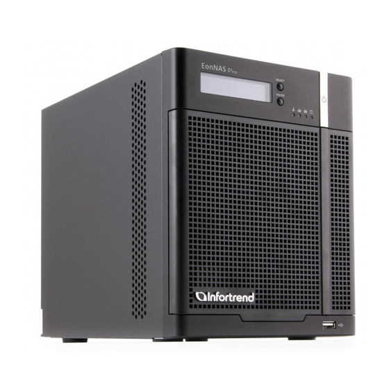
EonNAS Pro Series Hardware Manual Front Panel Overview The systems are ruggedly built and come in two (2), five (5) and eight (8) hard drive bay variations. The hard drive bay supports a single 3.5 inch SATA hard drive up to 3TB in storage capacity. -
Page 12: System Front Panel
EonNAS Pro Series Hardware Manual System Front panel 3 3 3 3 3 3 3 3 3 3 3 3 3 3 3 3 3 3 3 3 3 3 3 3 3 3 3 3 3 3 3 3... - Page 13 EonNAS Pro Series Hardware Manual The Select button is used for browsing system menus. Select button The system status LED warns users system faults. System status LED The LED indicates the status of the Ethernet 1 connection. Ethernet 1 LED The LED indicates the status of the Ethernet 2 connection.
-
Page 14: System Rear Panel
EonNAS Pro Series Hardware Manual System Rear panel EonNAS 500 /800 510 / 810 Item Description Power socket The power socket is for power cable connection. The eSATA port is for external expansion purposes eSATA port (intended for high speed external hard disk drive storage... - Page 15 EonNAS Pro Series Hardware Manual The USB ports are for external expansion purposes (CD, USB ports DVD, USB flash drives, printers, etc.); or to supply power to external eSATA devices. Ethernet port 1 Ethernet port 1 is used for accessing and configuration.
- Page 16 EonNAS Pro Series Hardware Manual Additional 10Gb iSCSI Expansion Ports For selected models that has two additional 10Gb iSCSI host ports. From left to right are CH3 and CH4 10Gb iSCSI host ports.
-
Page 17: Hard Drive Designation
EonNAS Pro Series Hardware Manual Hard Drive Designation The hard drives are placed in numeric order from top to bottom. When installing hard drives, always install to the top empty tray(s) and work your way down in order! -
Page 18: Front Panel Led Definitions
EonNAS Pro Series Hardware Manual Front Panel LED Definitions SELECT ENTE R BACKUP Systems without LCD Systems with LCD Front Panel LEDs Item LED Color & Status indicates the system has powered on Blue Power button Off indicates the system has powered off... -
Page 19: Drive Tray Leds
EonNAS Pro Series Hardware Manual Drive Tray LEDs Two (2) LED indicators are located on the right hand side of each drive tray. When notified by a drive failure message, you should check the drive tray indicators to find the exact failed drive. -
Page 20: Ethernet Port Leds
EonNAS Pro Series Hardware Manual Ethernet Port LEDs 200 / 500 / 800 210 / 510 / 810 Status indicates data transfer activity Activity LED Blinking amber indicates connection established Steady green Link Status Off indicates connection not established... -
Page 21: 1Gbps Iscsi Host Ports (Selected Models Only)
EonNAS Pro Series Hardware Manual 1Gbps iSCSI Host Ports (selected models only) LED Color & Status indicates 1000 Mb connection established. Steady green Link Status Off indicates 10/100 Mb connection established. indicates data transfer activity. Blinking amber Activity LED Off indicates there is no I/O activity. -
Page 22: 10Gbps Iscsi Host Ports (Selected Models Only)
EonNAS Pro Series Hardware Manual 10Gbps iSCSI Host Ports (selected models only) LED status Color LED Color & Status indicates a link has been Steady green Green Steady ON established Flashing Green indicates an active link Flashing green Off indicates a link has not been established The 10Gbps host connectivity is achieved by inserting SFP+ into the SFP+ cages on iSCSI ports and data signals are sent through optical cables. - Page 23 EonNAS Pro Series Hardware Manual The following transceiver and cables have been tested and proven to be compatible with your systems. Item part number Description IFT-9370CSFP10G-0010 Small Form Pluggable 10Gb Optical Transceiver Optical FC cable, LC-LC, MM-62.5/125, Duplex, LSZH, IFT-9270CFCCab01 O.D.=1.8mmx2, 1 Meter...
-
Page 24: Hardware Installation
EonNAS Pro Series Hardware Manual Hardware Installation Component Compatibility The use of compatible components is strongly recommended to ensure compatibility, quality and normal operation with your system. Please contact your vendor for a list of compatible components. Before You Start Items received in the package: ... -
Page 25: Installing Hard Drives
EonNAS Pro Series Hardware Manual Installing Hard Drives Hard drives are purchased separately. When purchasing hard drives, please consider the following factors: Hard Disk Drive Prerequisites Capacity (MB/GB): Use hard drives that have the same capacity and rotation speeds. RAID arrays use a “least-common-denominator” approach meaning the maximum capacity used in each drive for comprising a logical configuration is the maximum capacity of the smallest drive. -
Page 26: Drive Tray Numbering Sequence
EonNAS Pro Series Hardware Manual Drive Tray Numbering Sequence Tray numbering sequence is important because if any faults occur to disk drives, you should be able to identify the location of a faulty drive. Below is a list of the level of... -
Page 27: Installing Hard Drive Into The Drive Tray
EonNAS Pro Series Hardware Manual Installing Hard Drive into the Drive Tray 1. Open the front panel of the system. 2. Press the release button (indicated by the arrow) on the bezel, the bezel blue panel should open automatically and gently pull out the hard drive tray. - Page 28 EonNAS Pro Series Hardware Manual 4. With the tray bezel open, insert the hard drive and tray into the system enclosure. 5. Close the tray bezel. 6. Use the small flat blade screwdriver to turn the bezel lock from the unlock to lock position.
-
Page 29: Connections, Powering-On & Initialization
EonNAS Pro Series Hardware Manual Connections, Powering-on & Initialization Connecting the NAS System NOTE Make sure you have at least installed one hard drive into the NAS system. The system connection requires the user to (1) Connect an Ethernet cable from the NAS system to a switch / router (2) Place the CD that came with the system into your PC’s CD-ROM... -
Page 30: Powering On The System For The First Time
EonNAS Pro Series Hardware Manual Powering On the System for the First Time The initialization process only occurs if it is the first time you power on your system. Before you power-on, please make sure you have done the following: 1. -
Page 31: Powering-On The System & Initialization
EonNAS Pro Series Hardware Manual Powering-on the System & Initialization WARNING Hard drive data will be erased! NOTE Turn off Windows firewall: To turn off the Windows firewall, please refer to the instructions below. Windows 7/ Vista: Click on the Start button > Control Panel > Security > Windows Firewall >... - Page 32 EonNAS Pro Series Hardware Manual 4. The “Set IP” button will light up. Click on it so the NasFinder can set an IP address for your EonNAS system. 5. The IP settings window appears with an IP address, click the Connect button, the following browser window will appear.
- Page 33 EonNAS Pro Series Hardware Manual 7. The following screen will appear. Fill in your system’s settings. Host Name: Enter a unique name for your EonNAS system. Timezone: Select your local time zone. Password: Enter a new password for the admin account. (default: admin)
- Page 34 EonNAS Pro Series Hardware Manual click the Next button. Folder Access Rights Read Only Full Control E on S hare Full Control Read Only Full Control Read Only Click the “Next” button. 12. V iew the summary of configurations. Click Back to modify the parameters or Apply to complete the Startup Wizard.
-
Page 35: Quick Initialization Using Systems' Lcd Screen
EonNAS Pro Series Hardware Manual Quick Initialization Using Systems’ LCD Screen NOTE The quick initialization method is NOT the recommended way to initialize the system as default settings will be applied. Changes can later be made using its GUI interface. -
Page 36: Setting Up The System Using Lcd Screen Menu
EonNAS Pro Series Hardware Manual Setting up the System Using LCD Screen Menu This section describes the menus and sub-menus shown on the LCD module and how to setup and change the settings within. Due to the vast menus and sub-menus that are available on the LCD module, it is recommended that users NOT use the LCD module to set up the system. -
Page 37: Main Menu
EonNAS Pro Series Hardware Manual Main Menu For systems with a LCD screen, it provides users with basic system statuses and TCP/IP configuration settings. To setup specific settings, users need to log into the web user interface (please refer to the Web Interface Manual). -
Page 38: Tcp/Ip - Lan1 / Lan2 Menu
EonNAS Pro Series Hardware Manual TCP/IP – LAN1 / LAN2 Menu From the Main Menu, press the “SELECT” button to reach the TCP/IP menu and press the “ENTER” button to go into the TCP/IP sub-menu (LAN 1 example is shown below). -
Page 39: Lan 1 - Enter Settings Menu
EonNAS Pro Series Hardware Manual LAN 1 – Enter Settings Menu If LAN 1 did not establish a connection, the following menus will appear: SELECT SELECT SELECT Main menu TCP / IP LAN1-IP address ENTER ENTER ENTER NEtwork LAN1 0.0.0.0... - Page 40 EonNAS Pro Series Hardware Manual Once you are in the “LAN 1 Enter Settings” screen, you can configure detail LAN settings (settings can also be configured using the web interface, please refer to the Web Interface Manual). SEL ECT SELECT...
-
Page 41: Gateway Menu
EonNAS Pro Series Hardware Manual Gateway Menu There are Gateways -0, -1, -2 menus and if a gateway has been setup, the menus will show “Local host” and when setup, it will show an IP address: SELEC T SELEC T... - Page 42 EonNAS Pro Series Hardware Manual Once you are in the “Gateway Local host” screen, you can configure detail gateway settings (settings can also be configured using the web interface, please refer to the Web Interface Manual). SELECT TCP / IP...
- Page 43 EonNAS Pro Series Hardware Manual If a Gateway has been setup, an “IP address (xxx.xxx.xxx.xxx)” will appear in the menus. Once you are in the “Gateway-1 [IP address]” screen, you can change the gateway settings (settings can also be configured using the web interface, please refer to the Web-Interface Manual).
-
Page 44: Dns Menu
EonNAS Pro Series Hardware Manual DNS Menu The path to the DNS screen is shown below: SELECT SELECT SELECT Main menu TCP / IP TCP / IP ENTER ENTER ENTER Network LAN 1 LAN 2 SELECT SELECT SELECT TCP / IP... - Page 45 EonNAS Pro Series Hardware Manual If a DNS has been setup, an “IP address (xxx.xxx.xxx.xxx)” will appear in the menus. Once you are in the “DNS-x [IP address]” screen, you can change (add or delete) the DNS settings. Deleting adding any one of the DNS settings will bring you back to the main “TCP / IP DNS”...
-
Page 46: Physical Disk Menu
EonNAS Pro Series Hardware Manual Physical Disk Menu The Physical disk menu does not have user configurable settings. The numbers of hard drives that will appear when you press the “SELECT” button depends on the number of hard drives installed. -
Page 47: Pool Menu
EonNAS Pro Series Hardware Manual Pool Menu The pool menu does not have configuration settings. When users press “ENTER” to access the pool sub-menu, it displays the current pool(s) created. In the example below, it shows a pool with storage capacity configured in RAID 5... -
Page 48: System Menu
EonNAS Pro Series Hardware Manual System Menu The System menu has no user configurable settings. It displays system statuses such as CPU temperatures and system fan’s operational speeds. SELECT E o n N A S _ P r o _ x x x E NT ER x x x . -
Page 49: Shutdown
EonNAS Pro Series Hardware Manual Shutdown Press the “Enter” button to bring up the confirmation screen (Yes or No). Press the “Select” button to choose yes or no and the “Enter” button to make your selection. The system will sound one beep before shutting down. If you press Enter while selecting: ... -
Page 50: Reboot
EonNAS Pro Series Hardware Manual Reboot Press the “ENTER” button to bring up the confirmation screen (yes or no). Press the “SELECT” button to choose yes or no and the “ENTER” button to make your selection. When you press the ENTER button with the arrow pointing at: ... -
Page 51: Connections
EonNAS Pro Series Hardware Manual Connections Component Compatibility The use of compatible components is strongly recommended to ensure compatibility, quality and normal operation with your system. Please contact your vendor for a list of compatible components. Connection Concept Use CAT5e or better quality Ethernet cables, router and switch to construct your Ethernet network. -
Page 52: Esata External Expansion Port
EonNAS Pro Series Hardware Manual eSATA External Expansion Port eSATA devices are hot-swappable. The eSATA port can be used for external hard drive expansion (connecting to eSATA capable enclosures) or other eSATA capable devices. Most eSATA devices gain operating power from USB ports. It is essential to plug in the eSATA connector to the eSATA device and to the eSATA port before powering on (connecting USB connectors or an adaptor to supply power). -
Page 53: Usb External Expansion Port
EonNAS Pro Series Hardware Manual USB External Expansion Port USB devices are hot-swappable. The USB ports on the back of NAS systems can be used for external storage expansion purposes or peripheral devices. For USB expansion or peripheral device details, please refer to the manual that came with your USB device. -
Page 54: Usb Quick Backup Functionality
EonNAS Pro Series Hardware Manual USB Quick Backup Functionality The USB port located at the bottom right corner can be used for One-Touch Copy. Users MUST setup their systems beforehand to perform this task (please refer to the Web Interface Manual). You can find the One-Touch Copy settings under the following directory: Backup >... -
Page 55: For Systems With A Lcd Screen
EonNAS Pro Series Hardware Manual For systems with a LCD screen Simply plug in a USB flash drive to the front USB port and the LCD will display the following: SELECT O n e t o u c h c o p y ? ENTER - >... -
Page 56: Maintenance
EonNAS Pro Series Hardware Manual Maintenance WARNING Replace a failed hard disk drive from the system as soon as possible to ensure data redundancy. When inserting a hard drive, do not use excessive force. Forcing the hard drive can damage the connector pins either on the hard drive itself or the backplane within the system enclosure. - Page 57 EonNAS Pro Series Hardware Manual 3. Open the tray bezel by pushing the release button (indicated by the blue arrow) and the front bezel will automatically open. 4. Remove the drive tray by pulling it one inch away from the drive bay. Wait for at least 30 seconds for the hard drive to spin-down, and then gently and carefully remove the drive tray from the chassis.
-
Page 58: System Error Buzzer
EonNAS Pro Series Hardware Manual System Error Buzzer Note: For systems without a LCD screen, if you hear an error buzzer, please log into the system through a browser and check the system log. The LCD module provides basic action(s) and monitoring statuses only, it is... -
Page 59: Buzzer Sounds
EonNAS Pro Series Hardware Manual Open the front system panel cover and check all hard drive status LEDs. Normal operation hard drive’s power status LED should light up green, failed hard drive power status LEDs will light up red. Once you have located the failed hard drive, remove it out of the system and... - Page 60 EonNAS Pro Series Hardware Manual The following occurs when the alarm sounds but is not attended to within 30 seconds. The “Mute Buzzer -> Yes No” screen will be replace with the “System Error! Check Logs” screen while the alarm continues to sound and the system status LED lights red.
-
Page 61: Restore Default Settings
EonNAS Pro Series Hardware Manual Restore Default Settings Under the following circumstances, you may need to restore to system default settings: You forgot your password and you are unable to access the NAS server Note: Restoring the system to its default settings should be your last option. The restore default function will disable Jumbo Frame, reset port trunking settings and reset the “Admin”... -
Page 62: Appendix
EonNAS Pro Series Hardware Manual Appendix Technical Specifications Hardware EonNAS Pro 2x0: 102(W) x 245 (D) x 150 (H) mm Dimensions EonNAS Pro 5x0: 175(W) x 245(D) x 225(H) mm EonNAS Pro 8x0: 175(W) x 245(D) x 310(H) mm EonNAS Pro 850 series: 175(W) x 380(D) x 310(H) mm... -
Page 63: Operating Environment
EonNAS Pro Series Hardware Manual Operating Environment Temperature Operating: 5 to 40ºC (32º F to 104º F); Humidity Operating: 5% to 80%, non-condensing Host Port Pinouts EonNAS EonNAS EonNAS EonNAS EonNAS Interface Pro 2x0 Pro 5x0 Pro 8x0 Pro 8x0-1... -
Page 64: 1Gbps Ethernet Host Port
EonNAS Pro Series Hardware Manual 1Gbps Ethernet Host Port Name Name BI_DA+ BI_DC- BI_DA- BI_DB- BI_DB+ BI_DD+ BI_DC+ BI_DD- NOTE Automatic MDI/MDI-X Crossover: Crossover can be implemented internally at hub or switch or externally through twisted pair media. -
Page 65: 1Gbps Iscsi Host Port
EonNAS Pro Series Hardware Manual 1Gbps iSCSI Host Port Name Name BI_DA+ BI_DC- BI_DA- BI_DB- BI_DB+ BI_DD+ BI_DC+ BI_DD- NOTE Automatic MDI/MDI-X Crossover: Crossover can be implemented internally at hub or switch or externally through twisted pair media. -
Page 66: 10Gbps Iscsi Host Port
EonNAS Pro Series Hardware Manual 10Gbps iSCSI Host Port Name Description Transmitter ground Transmitter fault indication – High indicates a fault condition FAULT Transmitter Disable – Module electrical input disables on high or open MOD_DEF(2) Module definition 2 – Two wire serial ID interface data line (SDA) MOD_DEF(1) Module definition 1 –... - Page 67 EonNAS Pro Series Hardware Manual Receiver ground Receiver power +3.3V Transmitter power +3.3V Transmitter ground Transmitter DATA In Inverse Transmitter Data In Transmitter Ground...
-
Page 68: Certifications
EonNAS Pro Series Hardware Manual Certifications Safety UL (60950-1 2’nd) BSMI CNS 14336: 2005 IEC 60950-1, 2’nd Edition GOST-R GOST R 60950-1-2005 EN 55022: 2006/A1:2007 EN 55024:1998/A1:2001/A2:2003 EN 61000-3-2:2006/A1:2009/A2:2009 EN 61000-3-3:2008 BSMI (CNS 13438) FCC (FCC Part 15,subpart B )
Need help?
Do you have a question about the EonNAS Pro Series and is the answer not in the manual?
Questions and answers