Table of Contents
Advertisement
Advertisement
Table of Contents

Related Manuals for Infortrend EonNAS 1000 Series


Summary of Contents for Infortrend EonNAS 1000 Series
- Page 1 Infortrend EonNAS 1000 Series Version 2.2...
-
Page 2: Copyright Notice
Infortrend Technology, Inc. Disclaimer... -
Page 3: Legal Information
Infortrend, shall be subject to the latest Standard Warranty Policy available on the Infortrend website: http://www.infortrend.com/global/Support/Warranty Infortrend may from time to time modify, update or upgrade the software, firmware or any accompanying user documentation without any prior notice. Infortrend will provide access to these new software, firmware or documentation releases from certain download sections of our website or through our service partners. -
Page 4: Contact Information
Technical Support, Website Europe (EMEA) Infortrend Europe LTD. 5 Ringway Centre, Edison Road, Basingstoke, Hampshire, RG21 6YH, UK 305-220 305-221 Tel: +44-1256- Fax: +44-1256- Email, Technical Support, Website Germany/ Infortrend Deutschland GmbH Tel: +49-89-2070-42650 Fax: +49-89-2070-42654 Email, Technical Support, Website... -
Page 5: About This Manual
About This Manual About This Manual This manual introduces the hardware components of EonNAS system and describes how to install and maintain them. For components that are not user-serviceable: Contact our support sites. Software operation: Consult the User Manual in the CD-ROM. Revision History Version Date... -
Page 6: Safety Precautions
Safety Precautions Safety Precautions Read these instructions carefully before you install, operate, or transport EonNAS. Installation and Operation Install the rack cabinet and the associated equipment at a site where the ambient temperature stays lower than 35°C. Install the power source socket outlet near the enclosure where it is easily accessible and ground the rack cabinet. -
Page 7: Esd Precautions
ESD Precautions ESD Precautions Handle the modules by their retention screws, ejector levers, or the module’s metal frame/faceplate only. Avoid touching the PCB boards or connector pins. Use a grounded wrist strap and an anti-static work pad to discharge static electricity when installing or operating the enclosure. -
Page 8: Service And Maintenance
Service and Maintenance Service and Maintenance Keep the faulty module in place until you have a replacement unit in hand; an empty module greatly affects the efficiency of the airflow within the enclosure. During service operation, place the enclosure on soft and clean surface to prevent damaging its exterior. -
Page 9: Table Of Contents
Table of Contents Table of Contents Copyright Notice .......................2 Legal Information ......................3 Contact Information ....................4 About This Manual ......................... 5 Safety Precautions ......................... 6 Installation and Operation ..................... 6 Important Notice ........................6 ESD Precautions ........................7 Service and Maintenance ...................... 8 Introduction .................... - Page 10 Table of Contents Connections ....................47 System Connections for Initialization ..............47 JBOD Connections ....................48 Status LED When Powered-on ................49 EonNAS Initialization Process ................50 Connection Concept ....................53 eSATA Port ........................ 54 USB External Expansion Port .................. 55 Front Panel Quick Backup USB Port &...
-
Page 11: Introduction
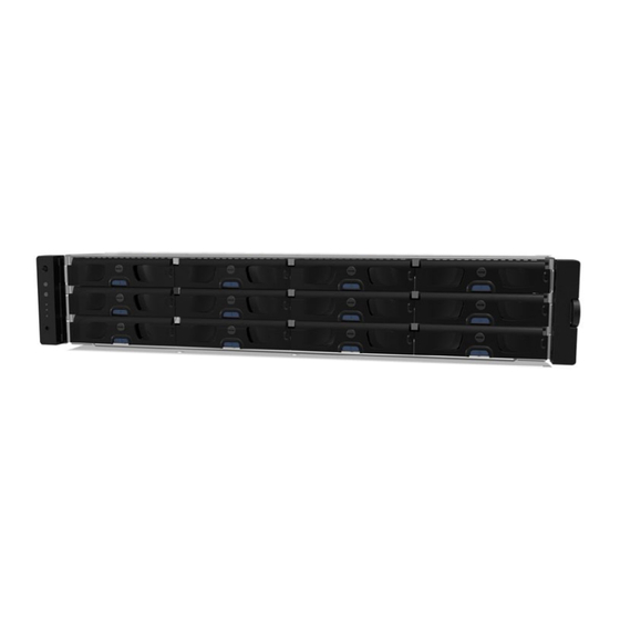
1.1.1 Front panel From top to bottom, the EonNAS 1000 series consists of 1U and 2U systems. Looking at the front panel, there is a set of status LEDs / power button (2) and hard drive slots (5). Dedicated to the 1U system’s front panel, there is a power button (1), a quick backup USB port (3) and a quick backup button (4) accessible by the user on the front panel. -
Page 12: Rear Panel
EonNAS 1000 Series Hardware Manual 1.1.2 Rear panel For detail EonNAS 1000 series rear connections, please refer to the illustration and table below. 3 3 3 3 3 3 3 3 3 3 3 3 3 3 3 3 3 3 3 3... - Page 13 EonNAS 1000 Series Hardware Manual Item / component Description VGA port VGA output connector. Restore default The restore default button is for restoring the system to button manufacturing settings (TCP / IP, system settings, etc.), please refer to “Restore Default Settings”.
- Page 14 EonNAS 1000 Series Hardware Manual...
-
Page 15: Eonnas System Front Status Panel
EonNAS 1000 Series Hardware Manual 1.1.3 1U EonNAS System Front Status Panel 3 3 3 3 3 3 3 3 3 3 3 3 3 3 3 3 3 3 3 3 No. & Item Color Status Position This LED indicates system 1. -
Page 16: 3U Eonnas System Front Status Panel
EonNAS 1000 Series Hardware Manual 1.1.4 2U / 3U EonNAS System Front Status Panel Name Color Status White indicates the system is being serviced or is requiring services. Service White OFF indicates the system is not being serviced nor is requiring services. - Page 17 EonNAS 1000 Series Hardware Manual has exceeded the safety threshold. Green indicates the system is operating normally. System Green fault Amber Amber indicates the system has encountered abnormal conditions: Press the button once mutes the audible alarm. Mute/ service Press and hold for more than two...
-
Page 18: Hard Drive Tray
EonNAS 1000 Series Hardware Manual 1.1.5 Hard Drive Tray The drive tray is designed to accommodate separately purchased 3.5-inch SAS or SATA interface hard disk drives. There is a rotary bezel lock (1) that secures the drive tray in chassis, while a release button (2) can be used when retrieving disk drives from the chassis. -
Page 19: Rear Panel Ethernet Port Leds
EonNAS 1000 Series Hardware Manual 1.1.6 Rear Panel Ethernet Port LEDs No. & Item Color Status 1. Link Steady green indicates connection established Green Status LED Off: indicates connection not established 2. Activity Amber Blinking amber indicates data transfer activity 1.1.7... -
Page 20: 10Gb Iscsi Expansion Host Ports (Sfp+)
EonNAS 1000 Series Hardware Manual 1.1.8 10Gb iSCSI Expansion Host Ports (SFP+) LED status Color LED Color & Status Steady green indicates a link has been Green Steady ON established Flashing Green Flashing green indicates an active link Off indicates a link has not been established For selected models that come with two 10Gbps iSCSI channel host ports. - Page 21 EonNAS 1000 Series Hardware Manual WARNING! The SFP transceiver from Infortrend contains a laser diode featuring class 1 laser (incompliance with Code of Federal Regulations (CFR), Title 21, Part 1040). All cables are sensitive and must be handled with care. To prevent interference within a rack system, the cable routing path must be carefully planned and the cables must not be bent.
-
Page 22: 10Gb Iscsi Expansion Host Ports (Rj45)
EonNAS 1000 Series Hardware Manual 1.1.9 10Gb iSCSI Expansion Host Ports (RJ45) Item Status Green indicates 10Gb connection established Speed LED Amber indicates 1Gb connection established Off indicates 10/100 connection established Green indicates connection established Link Status LED Flashing green... -
Page 23: 16Gb Fibre Expansion Host Ports
EonNAS 1000 Series Hardware Manual 1.1.10 16Gb Fibre Expansion Host Ports Item Status Green indicates connection established Link Status LED Flashing green indicates data activity Off indicates connection not established Green indicates 16Gb connection established Yellow indicates 8Gb connection Speed LED... -
Page 24: Psu / Cooling Module Leds
EonNAS 1000 Series Hardware Manual 1.1.11 PSU / Cooling Module LEDs The PSU (Power Supply Unit) contains the LEDs for the PSU and the cooling module statuses. When either of the unit fails, you need to replace the PSU as soon as possible. -
Page 25: System Monitoring Features
EonNAS 1000 Series Hardware Manual System Monitoring Features There are a number of monitoring approaches that provide the operating status of individual components. 1.2.1 Monitoring The EonNAS system can monitor the following: PSU Cooling module Cooling Module Speed Adjustment: If temperature reading(s) exceed the temperature threshold, the firmware automatically raises the rotation speed of all cooling fans. -
Page 26: Hot Swapping
EonNAS 1000 Series Hardware Manual Hot Swapping The system comes with a number of hot-swappable components that can be exchanged while the system is still online without affecting the operational integrity. These components should only be removed from the system when they are being replaced. -
Page 27: Hardware Installation
EonNAS 1000 Series Hardware Manual 2 Hardware Installation 2.4 Before You Start Some components are configured into fault-tolerant pairs and are independently hot-swappable while the failure of other components such as server board or the RAID controller can cause a down time. -
Page 28: Eonnas Slide Rail Installation (Optional)
EonNAS 1000 Series Hardware Manual 1U EonNAS Slide Rail Installation (Optional) The following table shows all accessories that came with the IFT-9277CSlider36 rackmount rail installation kit, it is designed for 1U enclosures and 24~36” deep racks. 2.5.1 IFT-9277 Kit Contents... -
Page 29: Installation Procedure
EonNAS 1000 Series Hardware Manual 2.5.2 Installation Procedure The installation of the IFT-9277 rack mount slide rail begins with assembling the slide rail (03) by inserting the rear bracket into the ditch (indicated by the blue circle) of the front brackets (01 & 02). - Page 30 EonNAS 1000 Series Hardware Manual Screw one M5 x 5mm position screw (05) to the front rack post and two M5 x 5mm position screws (05) to the rear rack post (top and bottom positions) to secure the slide rail to the rack.
-
Page 31: Removing The Enclosure
EonNAS 1000 Series Hardware Manual Attach one cage nut (08) to the front of the rack post. The cage nut will be used to secure the enclosure in place. Lift the enclosure and align it with the slide rails on the rack, keeping pressure even on both sides, slowly push the enclosure into the rack. -
Page 32: Eonnas Slide Rail Installation (Optional)
EonNAS 1000 Series Hardware Manual 2U EonNAS Slide Rail Installation (Optional) The following table shows all accessories that came with the IFT-9N1 rackmount rail installation kit. 2.6.1 IFT-9N1 Kit Contents Item Description Quantity Mounting bracket assembly, L-shape, left-side Mounting bracket assembly, L-shape, right-side... -
Page 33: Installation Procedure
EonNAS 1000 Series Hardware Manual 2.6.2 Installation Procedure The installation begins with installing the cage nuts (08) provided to be mounted onto the posts (if your rack post do not have threaded holes) for cross recess truss head screws M5 x 9.0mm (05) to secure the enclosure. Please refer to the illustration below that matches your enclosure dimensions. - Page 34 EonNAS 1000 Series Hardware Manual Secure the front end of the L-shape rail below the top cage nut (use for securing the enclosure). Extend the rail to the appropriate length where it meets the rear post and secure the front and rear using M5x0.9mm screws (05). Slide runner (indicated by the...
- Page 35 EonNAS 1000 Series Hardware Manual Attach the inner glides (03) to the left and right side of the enclosure using #6-32 L6 flathead screws (07). Rear of enclosure Top view Side view It is strongly recommended that two people perform this procedure together! To mount the enclosure onto the rail and into the rack, place the enclosure on the installed rails and slide it into the rack until the front ears of the enclosure meets the front rack posts.
- Page 36 EonNAS 1000 Series Hardware Manual Secure the enclosure by using two #6 32x10mm flathead screws at the rear and four M5 x30mm screws on the forearm handles (forearm handles can also be secured using M6 / 10-32 screws from the system accessory box).
-
Page 37: Removing The Enclosure
EonNAS 1000 Series Hardware Manual 2.6.3 Removing the Enclosure *Prior to removing the enclosure, power down your system (stop all I/O actions, please refer to Users’ manual) and all hard drives have been removed! *It is strongly recommended that two people work together on this procedure. -
Page 38: Eonnas 1000-1 Slide Rail Kit
EonNAS 1000 Series Hardware Manual EonNAS 1000-1 Slide Rail Kit The following table shows all accessories that came with the slide rail kit. 2.7.1 Kit Contents Item Description Quantity Mounting bracket assembly, left-side Mounting bracket assembly, right-side Inner glides Flathead screws #6-32 L4 Truss head screws M5 x9.0mm... -
Page 39: Installation Procedure
EonNAS 1000 Series Hardware Manual 2.7.2 Installation Procedure 1. The installation begins with determining the installation position (front and rear rack positions) and M5 cage nut (5) insertion location. Front rack posts Unit boundary 3U, M5 cage nut position M5 x 9.0mm... - Page 40 EonNAS 1000 Series Hardware Manual 2. Adjust the length by loosening the four screws on the slide rail. Secure the slide rails to front and rear posts using truss head screws. Tighten the four screws on the slide to fix the length.
-
Page 41: Removing The Enclosure
EonNAS 1000 Series Hardware Manual 2.7.3 Removing the Enclosure Prior to removing the enclosure, power down your system (stop all I/O actions, please refer to Users’ manual) and all hard drives have been removed! It is strongly recommended that two people work together on this procedure. -
Page 42: Installing Hard Drives
EonNAS 1000 Series Hardware Manual Installing Hard Drives Hard drives are purchased separately. When purchasing hard drives, please consider the following factors: 2.8.1 Prerequisites Capacity (MB/GB): Use hard drives that have the same capacity and rotation speeds. RAID arrays use a “least-common-denominator” approach meaning the maximum capacity used in each drive for comprising a logical configuration is the maximum capacity of the smallest drive. - Page 43 EonNAS 1000 Series Hardware Manual of the same brand, capacity, rotation speed and same model in an enclosure. RAID arrays use a “least-common-denominator” approach meaning the maximum capacity used in each drive for comprising a logical configuration is the maximum capacity of the smallest drive.
-
Page 44: Installing The Hard Drive To The Tray
EonNAS 1000 Series Hardware Manual 2.8.2 Installing the Hard Drive to the Tray To remove the tray from the enclosure, press the release button and gently pull out the tray. Place the hard drive into the drive tray. Make sure the hard drive is oriented that the drive’s interface connector is facing the open side of the drive tray and its label side... -
Page 45: Drive Tray Numbering Sequence
EonNAS 1000 Series Hardware Manual 2.8.3 Drive Tray Numbering Sequence 1U EonNAS Hard drive slot 1 Hard drive slot 2 Hard drive Slot 3 Hard drive slot 4 2U / 3U EonNAS Shaded hard drive slots may not be applicable to all 2U systems. -
Page 46: Inserting The Drive Tray Into The Enclosure
EonNAS 1000 Series Hardware Manual 2.8.4 Inserting the Drive Tray into the Enclosure Once the hard drives have been installed in the drive trays, the drive trays are ready to be installed into the system. With the tray bezel open, insert the installed hard drive and tray into the enclosure. -
Page 47: Connections
EonNAS 1000 Series Hardware Manual 3 Connections System Connections for Initialization NOTE Make sure you have at least installed ONE hard drive into the EonNAS system. It is strongly recommended that TWO hard drives are installed upon initialization! The system connection requires the user to (1) Connect an Ethernet cable from the EonNAS system to a switch / router (2) Place the CD that came with the system into your PC’s CD-ROM... -
Page 48: Jbod Connections
EonNAS 1000 Series Hardware Manual JBOD Connections NOTE For system that can connect to JBODs, please refer to the manual that came with the JBOD for instructions. A SAS host link cable is included per JBOD. If you need to purchase other cables or if you need other cable(s) of different length, please contact your vendor. -
Page 49: Status Led When Powered-On
EonNAS 1000 Series Hardware Manual Status LED When Powered-on Press the power button (shown below) 1U EonNAS front panel 2U / 3U EonNAS Front panel power button For 1U EonNAS systems The system status LED should remain off to indicate the system is operational and the Ethernet 1 &... -
Page 50: Eonnas Initialization Process
EonNAS 1000 Series Hardware Manual 3.4 EonNAS Initialization Process NOTE Turn off Windows firewall: To turn off the Windows firewall, please refer to the instructions below. Windows 7/ Vista: Click on the Start button > Control Panel > Security > Windows Firewall >... - Page 51 EonNAS 1000 Series Hardware Manual 4. When the “Set IP” button lights up, it means EonOne will automatically assign a new IP address for your NAS system. Click on it and wait for Set IP settings windows to appear. 5. The IP settings window appears with an IP address, click the OK button.
- Page 52 EonNAS 1000 Series Hardware Manual Gateway Interface IP Address Netm ask Link DHCP LAN1 LAN2 DHCP 9. Enter a unique pool name, select the protection level, and click the Next button. Pool Nam e: Pool-1 Data Pro tection L evel: Best Protection RAID 1: Provides best protection.
-
Page 53: Connection Concept
N AS iSCSI / Fibre switch The system connection concept of EonNAS 1000 series is shown above where it connects to multiple client PCs through a iSCSI / Fibre switch or router and for selected systems, they provide additional host connections, indicate by the blue line connecting to the shaded area. -
Page 54: Esata Port
EonNAS 1000 Series Hardware Manual eSATA Port eSATA devices are hot-swappable. Users should hear a beep sound when an e-SATA device is plugged-in and properly detected. The eSATA port can be used for external hard drive expansion (connecting to eSATA capable enclosures) or other eSATA capable devices. -
Page 55: Usb External Expansion Port
EonNAS 1000 Series Hardware Manual USB External Expansion Port USB devices are hot-swappable. Users should hear a beep sound when a USB device is plugged-in and properly detected. 1U 1000 EonNAS systems 2U 1000 EonNAS systems 2U / 3U 1000-1 EonNAS systems Specific models have USB3.0 ports (shown in green) labeled... - Page 56 EonNAS 1000 Series Hardware Manual The front USB port can also be used for external storage medium expansion purposes or peripheral devices. For details, please refer to the documents on the CD-ROM or the manual of your USB device.
-
Page 57: Front Panel Quick Backup Usb Port & Button (1U Eonnas Only)
EonNAS 1000 Series Hardware Manual Front Panel Quick Backup USB Port & Button (1U EonNAS only) The front USB port can be used for One-Touch Copy. Users need to setup their systems beforehand to perform One-Touch Copy. Log into the EonNAS management page and the settings can be found under “Backup >... -
Page 58: System Maintenance
EonNAS 1000 Series Hardware Manual 4 System Maintenance WARNING Replace a failed hard disk drive from the system as soon as possible! When inserting a removable module, do not use excessive force. Forcing or slamming a module can damage the connector pins either on the module itself or on the backplane. -
Page 59: Replacing The Hard Disk Drive
EonNAS 1000 Series Hardware Manual Replacing the Hard Disk Drive The easiest way to find out if your hard disk drive has failed is by looking at its status LED. If the power status lights up red, it indicates that the particular hard disk drive has failed. - Page 60 EonNAS 1000 Series Hardware Manual Remove the drive tray by pulling it one inch out of the drive bay and wait for at least 30 seconds for the disk drive to spin-down and then gently pull out the drive tray from the chassis.
-
Page 61: Replacing The Power Supply
EonNAS 1000 Series Hardware Manual 4.3 Replacing the Power Supply Power supplies are redundant and load-sharing. PSUs are hot swappable! Disconnect the power cord from the failed power supply. (Its LED should light static Red). Place your thumb around the left side of the PSU ejection lever (circled in red) while hooking your index and middle finger around the PSU handles (circled in blue). -
Page 62: Replacing The Power Supply (1000-1 Systems)
EonNAS 1000 Series Hardware Manual Replacing the Power Supply (1000-1 systems) The power supply units (PSU) are configured in a redundant configuration with each PSU housed in a robust steel canister. Detecting a Failed PSU If a PSU module fails, the system notifies you through the following indicators: ... - Page 63 EonNAS 1000 Series Hardware Manual 2. Loosen the retention screw that secures the extraction handle to the chassis. 3. To remove the PSU module, pull the extraction handle downwards to disconnect the PSU from the backplane connectors. Once dislodged, gently pull the PSU out of the system.
- Page 64 EonNAS 1000 Series Hardware Manual 4. Insert the replacement module. Make sure the extraction handle is pointing outwards. Push the replacement PSU into the chassis, and when you feel the contact resistance, push the extraction handle towards the PSU module and it should engage the back-end connectors.
-
Page 65: Restore Default Settings
EonNAS 1000 Series Hardware Manual Restore Default Settings Under the following circumstances, you may need to restore system default settings: • You forgot your password and you are unable to access the EonNAS server. NOTE Restoring the system to its default settings should be your last option. The restore default function will disable Jumbo Frame, reset port trunking settings and reset the “Admin”... -
Page 66: System Alarm Sound
EonNAS 1000 Series Hardware Manual System Alarm Sound The EonNAS system will sound alarm beeps to alert users that the system may be experiencing issues. The table below describes the type of beeps heard and what the issue(s) may be. When alarm sounds, please check the system log for details. -
Page 67: Appendix
Appendix Appendix Technical Specifications 1U EonNAS: 439(W) x 511 (D) x 43 (H) mm Dimensions 2U EonNAS: 445.6(W) x 650.25 (D) x 88.0 (H) mm 3U EonNAS: 445mm (W) x 514mm (D) x 130mm (H) 1U EonNAS: 4 hot-swappable 3.5” SATA HDDs Storage 2U EonNAS: 8 / 12 hot-swappable 3.5”... -
Page 68: Certifications
EonNAS 1000 Series Hardware Manual Certifications Summary BSMI FCC /CE Class A EMC / Safety UL60959/ IEC 60950 GOST WARNING An incorrect battery replacement (wrong specification) may result in short-circuit or explosion! To replace a battery, always purchase from the system vendor or only use batteries with specifications matching or recommended by the system vendor.
Need help?
Do you have a question about the EonNAS 1000 Series and is the answer not in the manual?
Questions and answers