Table of Contents
Advertisement
Advertisement
Table of Contents

Related Manuals for Infortrend EonStor DS 4000 Series


Summary of Contents for Infortrend EonStor DS 4000 Series
- Page 1 Infortrend EonStor DS 4000 Series Hardware Manual...
-
Page 2: Legal Information
Infortrend, shall be subject to the latest Standard Warranty Policy available on the Infortrend website: http://www.infortrend.com/global/Support/Warranty Infortrend may from time to time modify, update or upgrade the software, firmware or any accompanying user documentation without any prior notice. Infortrend will provide access to these new software, firmware or documentation releases from certain download sections of our website or through our service partners. -
Page 3: Contact Information
435 Lakeside Dr. Sunnyvale, CA. 94085, USA Tel: +1-408-988-5088 Fax: +1-408-988-6288 Email, Technical Support, Website Infortrend Technology, Ltd. / Infortrend 北京分公司 China 北京市朝阳区东四环中路远洋国际中心 D 座 403 室 Room 403,Block D, Ocean International Center, Dis. Chaoyang, Beijing, China Tel: +86-10-6310-6168 Fax: +86-10-59648252 Email,... -
Page 4: Copyright Notice
Infortrend, the Infortrend logo, SANWatch, ESVA, EonStor DS, EonStor DS, EonNAS, and EonPath are registered trademarks of Infortrend Technology, Inc. Other names prefixed with “IFT” and “ES” are trademarks of Infortrend Technology, Inc. Windows is a registered trademark of Microsoft Corporation. -
Page 5: Safety Precautions
Safety Precautions Safety Precautions Read these instructions carefully before you install, operate, or transport the EonStor DS RAID system and JBODs. Installation and Operation Install the rack cabinet and the associated equipment at a site where the ambient temperature (special room cooling equipment may be required) stays lower than: a. -
Page 6: Service And Maintenance
The use of Infortrend certified components is strongly recommended to ensure compatibility, quality and normal operation with your Infortrend products. Please contact your distributor for a list of Infortrend certified components (eg. SFP, SFP+, HBA card, iSCSI cable, FC cable, memory module, etc.). -
Page 7: Esd Precautions
ESD Precautions ESD Precautions Handle the modules by their retention screws, ejector levers, or the module’s metal frame/faceplate only. Avoid touching the PCB boards or connector pins. Use a grounded wrist strap and an anti-static work pad to discharge static electricity when installing or operating the enclosure. -
Page 8: About This Manual
About This Manual About This Manual The manual introduces hardware components of EonStor DS RAID and JBOD systems. It also describes how to install, monitor, and maintain them. For non-serviceable components, please contact our support sites. Firmware operation: Consult the Firmware User Manual on the CD-ROM. SANWatch software: Consult the SANWatch User Manual on the CD-ROM. -
Page 9: Table Of Contents
Table of Contents Table of Contents Legal Information ............. 2 Contact Information ..........3 Copyright Notice ............4 Safety Precautions ..........5 Installation and Operation ............... 5 Service and Maintenance ..............6 Important Notice ................6 ESD Precautions ................7 About This Manual ........... - Page 10 Table of Contents Model Variations ................18 Major Components ................ 20 RAID Controller and Interface ................ 20 JBOD Controller and Interface ............... 20 Power supply unit with built-in cooling module ..........21 The Rear Panel ................22 Dual Controller Models .................. 22 Single-Controller Models ................
- Page 11 Table of Contents PSU & Cooling Module (JB 3060L) ..........43 Cooling Module (JB 3060L) ............44 System Monitoring Features ............45 Expansion Enclosure Support ................ 45 I 2 C bus ......................46 Firmware (FW) and SANWatch ..............46 Audible Alarms ....................46 Hot-swapping ................
- Page 12 Table of Contents Installing the Controller .................. 62 System Connection ..........63 General Considerations on Making Connections ......63 Host-Side Topologies ..................64 Host-Side Parameters ..................64 Maximum Concurrent Host LUN Connection (“Nexus” in SCSI) ....65 Maximum Queued I/O Count ................. 66 Fibre-Host Connections ..............
- Page 13 Table of Contents JBOD Connections ................ 93 JBOD SAS Expansion Configuration ............. 93 Configuration Rules ..................94 Dual Controller Expansion Connection ............96 Dual Controller Expansion Connection (4U60 JBOD System) ...... 97 Dual Controller Expansion Connection (JB 3060L) ........98 Single Controller Expansion Connections .............
- Page 14 Table of Contents Controller LED for RAID Models ..............118 Controller LED for 12Gb/s SAS JBOD Models ..........120 iSCSI / Ethernet Management Port LEDs ............ 121 10Gb iSCSI Host Port LEDs (Fibre) ............122 10Gb iSCSI Host Port LEDs (RJ45) ............122 8Gb Fibre-Host Port LEDs ................
- Page 15 Table of Contents Replacing the Power Supply Module / Cooling Module ....142 Detecting a Failed PSU ................142 Replacing Power Supply Unit ..............143 Replacing the Power Supply Module (4U60 System)....145 Detecting a Failed PSU ................145 Replacing the PSU ..................146 Replacing the Power Supply Module (JB 3060L) ......
- Page 16 Table of Contents Kit Contents ....................159 Slide Rail Installation Procedure ..............160 Slide Rail System (4U60 System) ..........162 Adjuster Pillars (4U60 System) ..............162 Adjuster Pillar Installation (4U60 System) ........... 163 Slide Rail / Enclosure Installation (4U60 System) ........164 Slide Rail Contents ..................
-
Page 17: Introduction
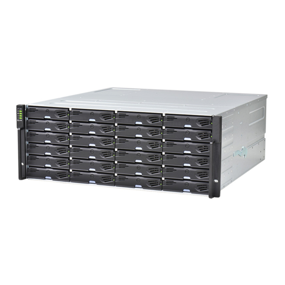
Introduction Product Overview This manual introduces EonStor DS 4000 systems that support 3 / 6 / 12 SAS, Near Lline SAS and SATA hard drives. The enclosure is designed to utilize 2.5” or 3.5” hard drives. Drive capacity can be expanded by attaching expansion hard drive enclosures (JBODs). -
Page 18: Model Variations
Model Variations Comprised of RAID and JBOD models, RAID systems store hard drives and control the entire storage array while JBOD systems connect to a master RAID system and allow storage capacity expansion by adding more hard drives. Hard drive limitation(s) may vary model to model. - Page 19 EonStorDS 1000 Series Rear view...
-
Page 20: Major Components
Major Components NOTE Upon receiving your system, check the package contents against the included Unpacking List. If module(s) are missing, please contact your system vendor immediately. The Cache Backup Module (CBM) is an optional feature in single controller systems. RAID Controller and Interface Each RAID controller comes with pre-installed DIMM module(s). -
Page 21: Power Supply Unit With Built-In Cooling Module
EonStorDS 1000 Series Power supply unit with built-in cooling module Cooling module is built into the power supply unit (PSU) to protect the system from overheating. The two hot-swappable PSUs provide constant power to the system. The modular nature of the system and the easy accessibility to all major components ensure ease of maintenance. -
Page 22: The Rear Panel
The Rear Panel Dual Controller Models Dual controller systems are indicated by an “R” in their model number (please refer Model Naming Conventions. In dual controller configuration, if one controller fails, the second controller module will take over in a manner that is transparent to application servers. - Page 23 EonStorDS 1000 Series The top controller (Controller A) is the primary controller. The bottom controller (Controller B) is the secondary (= redundant) controller which is idle during normal operation and takes over the management role when Controller A cannot function properly due to hardware error, controller module removal, etc.
-
Page 24: Single-Controller Models
Single-Controller Models Single-controller models are designated by a “G” or “S” in their model number. The second controller slot is filled with a dummy cage (D). The 2UL-C and 2UL model differs in the additional cooling module at the center-bottom position. -
Page 25: Upgrading Single Controller To Dual Controller System
EonStorDS 1000 Series Upgrading Single Controller to Dual Controller System If the model name of a single controller RAID/JBOD is designated with the letter “S”, it can be upgraded into a dual-controller configuration by adding another controller module and firmware upgrade (see software manual). If the model name is designated with a “G”, it is not upgradeable to a dual controller configuration. -
Page 26: Chassis
Chassis The chassis is rugged constructed and divided into front and rear sections. The chassis is designed to be installed into a rack or cabinet. Front Panel Hard drive trays / drawers (1): Each drive tray is hot-swappable and... - Page 27 EonStorDS 1000 Series holds a 3.5-inch hard drive. 4U60 systems have 3 drawers, holding 20 hard drives in each drawer. The hard drive trays of JB2060L / JB 3060L are accessible from the top of the enclosure by sliding the top cover to the rear.
-
Page 28: Rear Panel
Rear Panel Description Description Controller A Power supply + cooling module Controller B or dummy cage Cooling module... -
Page 29: Internal Backplane
EonStorDS 1000 Series Controllers (1) / (2): Each RAID controller module contains a main circuit board and a pre-installed DIMM module. For single controllers, a dummy cage will be placed at the controller (2) position. The host port configurations will vary. For details, see Rear Panel Components. -
Page 30: Front Panel Components
Front Panel Components LED Panel The LED panel can be located on the chassis ear. The LED panel contains Service LED (1), a power supply status LED (2), cooling module status LED (3), temperature sensor status LED (4), System fault LED (5), Mute Service button (6), rotary ID switch (for JBOD) (7). -
Page 31: Led Panel (4U60 System)
EonStorDS 1000 Series LED Panel (4U60 System) The LED panel on a 4U60 JBOD storage expansion system can be located on the chassis ear. The LED panel contains Service/ Mute LED & button (1), a power supply status LED (2), cooling module status LED (3), temperature sensor status LED (4), System fault LED (5) and rotary ID switch (6). -
Page 32: Drive Tray Bezel
Drive Tray Bezel 2.5 inch 3.5 inch The drive tray is designed to accommodate separately purchased SAS or SATA interface hard disk drives. There is a rotary bezel lock (1) that secures the drive tray in chassis, while a release button (2) can be used when retrieving disk drives from the chassis. -
Page 33: Hard Drive Drawer (4U60 System)
EonStorDS 1000 Series Hard Drive Drawer (4U60 System) Hard drive slot order WARNING DO try to fill all 60 hard drive slots with hard drives. When performing a maintenance task on hard drive(s), DO NOT remove more than one hard drive out of the drawer at a time. -
Page 34: Expansion Enclosure Jb 3060L
There are three hard drive drawers in the system and when viewed from the top, the first drawer on the left contains hard drives numbering from 1~20, the second drawer in the middle contains hard drives 21~40 and the third drawer on the right contains hard drives 41~60. -
Page 35: Rear Panel Components
EonStorDS 1000 Series Rear Panel Components Controller Module of RAID Models Designation Description Designation Description Host ports Controller status LED Battery backup unit / super Ethernet management port capacitor SAS expansion port Serial port Restore default button USB port Restore default LED The controller on the dual controller models also features a Cache Backup Module (CBM), consisting of a Battery Backup Unit (BBU) and Flash Backup Module (FBM). - Page 36 NOTE The management port supports only 100Mbs and 1000Mbs (1Gbs) speeds. Host boards are optional add-on components! There are two host board slots, if you are installing a host board for the first time, please install it to the slot on the left (next to SAS exp.
-
Page 37: Controller Module Of Jbod Models
EonStorDS 1000 Series Controller Module of JBOD Models The expansion JBOD controller features SAS expansion ports (1), SAS expansion port status LEDs (2), controller status LEDs (3), extraction levers (4) and miniUSB port (5). The expansion controller contains a circuit board within a metal canister, interfaced through hot-swap docking connectors at the back-end. - Page 38 The miniUSB port (5) serves no data storage purposes and is reserved for manufacturer use only. WARNING The only time you should remove the controller is to replace a failed controller. The controller is built of sensitive components and unnecessary tampering can damage the controller.
-
Page 39: Super Capacitor & Flash Backup Module
EonStorDS 1000 Series Super Capacitor & Flash Backup Module The super capacitor (1) and flash backup module (2) can be located inside the controller and serves similar functions to a Cache Backup Module (CBM) described in the previous section. With the super capacitor, the cached data can be kept safe for an extended period of time NOTE The super capacitor is only charged partially when shipped. -
Page 40: Psu & Cooling Module
PSU & Cooling Module The two redundant, hot-swappable PSU has a power socket (1), power switch (2), PSU status LED (3), cooling module (4), retention screw (5) and an extraction handle (6). The cooling modules can operate at three rotation speed settings. Under normal operating conditions, the cooling fans run at the low speed. -
Page 41: Psu & Cooling Module (4U60 System)
EonStorDS 1000 Series PSU & Cooling Module (4U60 System) The system is equipped with two redundant, hot-swappable PSUs at the rear section of the chassis. Each PSU comes with a (1) power socket and built-in (2) cooling modules to provide system with airflow. -
Page 42: Cooling Module (4U60 System)
Cooling Module (4U60 System) The system is equipped with three redundant, hot-swappable system cooling modules at the rear section of the chassis. The cooling module has an ejection lever (1) and a status LED (2) and an extraction lever (3). Should the status LED light up red, please arrange for a replacement immediately. -
Page 43: Psu & Cooling Module (Jb 3060L)
EonStorDS 1000 Series PSU & Cooling Module (JB 3060L) The system is equipped with two redundant, hot-swappable PSUs at the rear section of the chassis. Each PSU comes with a (1) power socket built-in cooling modules to provide the system with airflow. -
Page 44: Cooling Module (Jb 3060L)
Cooling Module (JB 3060L) cooling module accessible located inside the enclosure. To access it for maintenance replacement push the two release buttons (1) on the top cover simultaneously. Move the top cover gently backward (2). Please note, the cover cannot be removed in total from the enclosure. -
Page 45: System Monitoring Features
EonStorDS 1000 Series System Monitoring Features There are a number of monitoring approaches that provide the operating status of individual components. Expansion Enclosure Support Monitoring: A managing RAID system is aware of the status of JBOD components including those of: ... -
Page 46: I 2 C Bus
JBOD Enclosure Status Monitoring: A RAID system, when connected with expansion JBODs, acquires the component status within other enclosures via a proprietary enclosure monitoring service using the in-band connectivity. No additional management connection is required. C bus The detection circuitry and temperature sensors are interfaced through a non-user-serviceable I C bus. -
Page 47: Hot-Swapping
EonStorDS 1000 Series Hot-swapping The system comes with a number of hot-swappable components that can be exchanged while the system is still online without affecting the operational integrity. These components should only be removed from the system when they are being replaced. -
Page 48: Hardware Installation
Hardware Installation This chapter describes how to install modular components, such as hard drives into the enclosure and CBM into the RAID controller enclosure. NOTE Installation into a rack or cabinet should occur BEFORE hard drives are installed into the system. Installation Prerequisites Static-free installation environment: The system must be installed in a static-free environment to minimize the possibility of electrostatic discharge (ESD) damage. -
Page 49: Installation Procedures Overview
EonStorDS 1000 Series Make sure you are aware of the related positions of each plug-in module and interface connector. Cables must be handled with care and must not be bent. To prevent emission interference within a rack system and accidental cable disconnection, the routing paths must be carefully planned. -
Page 50: Unpacking The System
Unpacking the System Compare the Unpacking List included in the shipping package against the actual package contents to confirm that all required materials have arrived. Box contents For detail content(s), please refer to the unpacking list that came with the system. The accessory items include a serial port cable, screws, Quick Installation Guide, a CD containing the SANWatch management software and its manual and Firmware Operation Manual, and a product utility CD containing the Installation and... -
Page 51: Installing Hard Drive
EonStorDS 1000 Series Installing Hard Drive Installation of hard drives should only occur after the enclosure has been rack-mounted! Hard Drive Installation Prerequisites Hard drives are separately purchased and when purchasing hard drives, the following factors should be considered: Capacity (MB/GB): Use drives with the same capacity. RAID arrays use a “least-common-denominator”... - Page 52 MUX Board: Shown below, controller A (1) and controller B (2) is connected to the backplane (3). With a MUX board (4) paired to the hard drive (5), data signals is able to switch between controllers A and B signal ports (indicated by the blue arrow / dotted line). Under normal circumstances, controller B signal port is in standby mode (6).
-
Page 53: Sas Interface
EonStorDS 1000 Series SAS Interface The SAS interface features a dual-ported connectivity with pins on both sides of its connector that include SAS primary links (1), power link (2) and underneath it, the SAS secondary links (3). The SATA drives have only one port that includes the SATA physical links (4) and the power link (5). -
Page 54: Hard Drive Designation
Hard Drive Designation Illustrations shown below are system hard drive slot number designations. Please familiarize yourself with the designations to avoid withdrawing the hard drive(s) out of the enclosure. 2U systems 3U systems 4U systems... - Page 55 EonStorDS 1000 Series JB 2060L / JB 3060L...
-
Page 56: Installing The Hard Drive Into Drive Tray
Installing the Hard Drive into Drive Tray Open the bezel by pressing the release button and gently pull out the tray. Place the hard drive into the drive tray, making sure that the interface connector is facing the open side of the drive tray and its label side facing up. If you have a MUX board and you want to install a SAS drive, the MUX board should be removed. -
Page 57: Installing The Hard Drive Tray Into The Enclosure
EonStorDS 1000 Series Installing the Hard Drive Tray into the Enclosure Once the hard drives have been installed in the drive trays, install the drive trays into the system. WARNING Each drive bay must be populated with a tray even if it does not contain a hard drive. With a bay empty, ventilation will be disrupted and the system will overheat. -
Page 58: Installing Hard Drive Brackets (4U60 System)
Installing Hard Drive Brackets (4U60 System) With the hard drive connector end facing downwards and the bottom of the hard drive label facing you, secure both brackets (1) with the supplied flathead screws (2). The bracket with the handle plate (3) should be on the right (with the HDD label facing you). -
Page 59: Installing Hard Drives Into The Drawer (4U60 System)
EonStorDS 1000 Series Installing Hard Drives into the Drawer (4U60 System) Once the hard drive brackets have been installed onto hard drives that are to be installed into the drawer, open the drawer 1 (situated on the left) insert each hard drive vertically (in a specific order) while using bracket handle. -
Page 60: Installing Hard Drives (Jb 3060L)
Installing Hard Drives (JB 3060L) To install hard drives into JB 2060L / 3060L you have to insert the hard drive into its respective drive tray first. Once the hard drive is in the right position 2 pins on each side will automatically push out secure the hard drive through its mounting holes. -
Page 61: Installing Host Boards
EonStorDS 1000 Series Installing Host Boards NOTE As an upgrade to existing single controller systems, down time may occur! For dual controller systems, please install to one controller at a time. ALWAYS install to the left host board slot (close to SAS Exp.) first before installing to the right host board slot! Shutdown (for single controller systems in operation) and remove the controller from the enclosure. -
Page 62: Installing The Controller
Installing the Controller Insert the controller slowly into the module slot. When you feel the contact resistance, use slightly more force and then push both of the ejection levers upwards (indicated by the blue arrows) to secure the controller into chassis. Secure the controller by fastening the two retention screws (1) under the ejection levers (2). -
Page 63: System Connection
EonStorDS 1000 Series System Connection This chapter outlines the general configuration rules you should follow when cabling a storage system and introduces basic information about topologies. You can use these topologies or refer to them as a guide for developing your own unique topologies. -
Page 64: Host-Side Topologies
include both SAS and SATA drives in a logical drive. A spare drive should have a minimum capacity that is equivalent to the largest drive that it is expected to replace. If the capacity of the spare is less than the capacity of the drive it is expected to replace, the controller will not proceed with the failed drive rebuild. -
Page 65: Maximum Concurrent Host Lun Connection ("Nexus" In Scsi)
EonStorDS 1000 Series Maximum Concurrent Host LUN Connection (“Nexus” in SCSI) The "Max Number of Concurrent Host-LUN Connection" menu option is used to set the maximum number of concurrent host-LUN connections. Maximum concurrent host LUN connection (nexus in SCSI) is the arrangement of the controller internal resources for use with a number of the current host nexus. -
Page 66: Maximum Queued I/O Count
Maximum Queued I/O Count The "Maximum Queued I/O Count" menu option enables you to configure the maximum number of I/O operations per host channel that can be accepted from servers. The predefined range is from 1 to 1024 I/O operations per host channel, or you can choose the "Auto"... -
Page 67: Fibre-Host Connections
EonStorDS 1000 Series Fibre-Host Connections WARNING All Fibre cables are sensitive and must be handled with care. To avoid interference, the cable routing path must be carefully planned and the cables must not be bent. The Fibre Channel standard allows optical connections. Optical cables can be used over longer distances and have been shown to be more reliable. - Page 68 WARNING The SFP transceiver contains a laser diode featuring class 1 laser. To ensure continued safety, do not remove any covers or attempt to gain access to the inside of the product. Refer all servicing to qualified personnel. FC port dust plugs Each FC port comes with a dust plug.
-
Page 69: Fibre-Host Topologies
EonStorDS 1000 Series Fibre-Host Topologies The Fibre Channel standard supports three (3) separate topologies. They are point-to-point, Fibre Channel Arbitrated Loop (FC-AL), and fabric switch topologies. Point-to-Point: Point-to-point topology is the simplest topology. It is a direct connection between two (2) Fibre Channel devices. ... -
Page 70: Fibre Cabling
Fibre Cabling Following are steps that should be completed with cabling: Maintain a configuration plan. In addition to cabling topologies and list of networking components, the plan can also include firmware and software maintenance details. Confirm that you have a Fibre Channel cable that loops 6-inch or longer. Ensure proper airflow and keep cables away from ventilation airflow outlets. -
Page 71: Simple End-To-End Connection
EonStorDS 1000 Series Simple End-to-End Connection HBA 0 HBA 0 HBA 1 HBA 1 EonPath EonPath CH0 B113 CH2 A112 CH2 B113 CH0 A112 CH3 A112 CH3 B113 CH1 B113 CH1 A112 CH2 A112 CH2 B113 CH0 A112 CH0 B113 CH1 B113 CH1 A112 CH3 A112... -
Page 72: Das (Direct-Attached) Connection
DAS (Direct-Attached) Connection NOTE If a logical drive can be accessed by different servers, file locking, FC switch zoning, port binding, and multipath access control will be necessary in order to avoid access contention. HBA 0 HBA 0 HBA 1 HBA 1 EonPath EonPath... - Page 73 EonStorDS 1000 Series With more disk drives over the SAS expansion links, you can create more logical groups of drives. These logical drives using more host channel IDs or LUN numbers. If a server has multiple data paths to a RAID system, a multi-path software is necessary, e.g., the EonPath driver.
-
Page 74: Switched Fabric Connection (Dual-Controller)
Switched Fabric Connection (Dual-Controller) NOTE A logical partition presented through LUN Mapping can be seen by all servers across SAN. Make sure you have access control such as file-locking, switch zoning, port binding, etc., to avoid access contention. HBA 0 HBA 1 HBA 0 HBA 1... - Page 75 EonStorDS 1000 Series Data path connection Fault-tolerant paths Host channel bandwidth 6400 MB/s Channel link bypass is provided on external FC switches. Each of the application servers shown in the diagram is equipped with two HBAs with FC links via two FC switches to the SFP ports on individual RAID controllers.
-
Page 76: Switched Fabric Connection (Single-Controller)
Switched Fabric Connection (Single-Controller) HBA 0 HBA 1 HBA 0 HBA 1 EonPath EonPath CH0 B114 CH1 B114 CH0 A112 CH1 A112 CH0 B113 CH1 B113 CH0 A115 CH1 A115 7 8 9 1011 12 7 8 9 1011 12 1 2 3 4 5 6 1 2 3 4 5 6 CH0 A112... - Page 77 EonStorDS 1000 Series Above is the sample drawing showing connections with each SFP port connected to FC switches and then to host adapters. See logical associations in the drawing for LUN mapping details. Use Enclosure-specific spares to prevent a spare drive from participating in the rebuild of a logical drive on another enclosure.
-
Page 78: Sas-Host Connections
SAS-Host Connections NOTE Please consult your vendor or sales representative for compatible host link cables. Please contact your vendor to purchase host-link cables. SAS cables (28AWG x 8 pairs) are characterized by 100ohm, black colors, UL-approved, lead-free, 50, 120 or 170cm cable lengths; connectors can be secured to chassis receptacle using latching mechanism. -
Page 79: Das (Direct-Attached Storage) Connection With Redundant Host Path
EonStorDS 1000 Series DAS (Direct-Attached Storage) Connection with Redundant Host Path HBA 0 HBA 1 EonPath EonPath CH0 AID CH0 AID CH0 AID CH0 AID CH0 AID CH1 BID CH0 AID CH0 BID CH0 AID CH1 AID CH0 AID CH1 AID CH1 BID CH0 BID CH0 BID... - Page 80 HBA 0 HBA 1 EonPath CH0 AID CH1 AID CH0 AID CH1 AID RAID Single-controller models With more hard drives over the SAS expansion links, you can create more logical groups of drives. Avail these logical partitions using more LUN numbers. NOTE EonPath multipath software or Linux Device Mapper is necessary for controlling and optimizing the access to logical drives via multiple data paths.
-
Page 81: Das (Direct-Attached Storage) Connection To Two Servers
EonStorDS 1000 Series DAS (Direct-Attached Storage) Connection to Two Servers CH0 AID CH1 AID CH1 AID CH0 AID RAID NOTE If you would like a LUN (a logical partition) to be accessed by multiple hosts, file locking or multipath access control will be necessary. -
Page 82: Iscsi-Host Connections
iSCSI-Host Connections Ethernet cable requirements: Ethernet cables are user-supplied. Cat5e shielded STP type network cables or better performance types (important for meeting the requirements imposed by emission standards). Straight-through Ethernet cables with RJ-45 plugs. Use of cross-over cables can also be automatically detected and re-routed for a valid connection. -
Page 83: Network & Host Connection Topologies
EonStorDS 1000 Series Network & Host Connection Topologies The iSCSI host ports connect to Ethernet network devices and iSCSI initiators that comply with the IETF iSCSI standard (RFC 3720). Network connection of the iSCSI ports is flexible. The use of network connecting devices, subnet, Name Servers, or iSCSI management software can vary from case to case. -
Page 84: High Availability Ip San With Redundant Raid Controller
High Availability IP SAN with Redundant RAID Controller EonPath EonPath VLAN 1 VLAN 0 10 x 1 2x 1 0x 7 8 9 1 011 1 2 1 2 3 4 5 6 LD 0 LD 1 LD 2 LD 3 CH0 AID* CH1 AID* CH2 BID*... - Page 85 EonStorDS 1000 Series configuration using this configuration. For remote replication setup, please refer to “High Availability IP SAN “High Availability IP (Remote Replication Enabled) SAN with Port Trunk (Remote Replication Enabled)”. 4 logical drives (each has 4 member drives; for better performance, you can include drives from JBOD) LD0 mapped to CH0 AID and CH0 BID;...
-
Page 86: Single-Controller With Fault-Tolerant Path
Single-Controller with Fault-Tolerant Path HBA 0 HBA 1 HBA 0 HBA 1 EonPath EonPath CH2 ID0 CH2 ID0 CH0 ID0 CH0 ID0 CH3 ID0 CH3 ID0 CH1 ID0 CH1 ID0 CH2 ID1 CH2 ID1 CH0 ID1 CH0 ID1 CH3 ID1 CH3 ID1 CH1 ID1 CH1 ID1... -
Page 87: High Availability Ip San
EonStorDS 1000 Series High Availability IP SAN (Recommended Cabling Method for Remote Replication) EonPath EonPath VLAN 1 VLAN 0 10 x 11 x 1 2x 1 0 x 1 1x 12 x 7 8 9 1011 1 2 1 2 3 4 5 6 LD 0 LD 1 CH0 AID*... - Page 88 alternate paths to the same logical drive. 2 logical drives (each has 8 member drives). More logical drives can be created from drives in JBOD. LD0 mapped to CH0 AID, CH1 BID, CH2 AID and CH3 BID; LD has to be assigned to both controllers A and RAID configuration B to enable remote replication.
-
Page 89: High Availability Ip San With Port Trunk (Remote Replication Enabled)
EonStorDS 1000 Series High Availability IP SAN with Port Trunk (Remote Replication Enabled) EonPath EonPath VLAN 1 VLAN 0 10 x 11 x 1 2x 1 0 x 1 1x 12 x 7 8 9 1011 1 2 1 2 3 4 5 6 LD 0 LD 1 Ch0 AID... - Page 90 configuration logical drives can be created from drives in JBOD. LD0 mapped to CH0 AID and CH1 BID; LD has to be assigned to both controllers A and B to enable remote replication LD1 mapped to CH1 BID and CH0 AID; LD has to be assigned to both controllers A and B to enable remote replication...
Need help?
Do you have a question about the EonStor DS 4000 Series and is the answer not in the manual?
Questions and answers