
Related Manuals for Pilz PSSu E F PS2


Summary of Contents for Pilz PSSu E F PS2
- Page 1 PSSu E F PS2(-T)(-R) Decentralised system PSSuniversal I/O Operating Manual-1002237-EN-05...
- Page 2 Preface This document is a translation of the original document. All rights to this documentation are reserved by Pilz GmbH & Co. KG. Copies may be made for internal purposes. Suggestions and comments for improving this documentation will be gratefully received.
-
Page 3: Table Of Contents
Mechanical connection of the base modules Terminal configuration Connecting the module Section 7 Operation Messages Display elements 7.2.1 Display elements for module diagnostics 7.2.2 Display elements for the status of the module supply and periphery supply 26 Operating Manual PSSu E F PS2(-T)(-R) 1002237-EN-05... - Page 4 Contents Section 8 Technical details Section 9 Order reference Product Accessories Operating Manual PSSu E F PS2(-T)(-R) 1002237-EN-05...
-
Page 5: Introduction
Introduction Validity of documentation This documentation is valid for the product types PSSu E F PS2, PSSu E F PS2-T and PSSu E F PS2-R. It is valid until new documentation is published. This operating manual explains the function and operation, describes the installation and provides guidelines on how to connect the product. -
Page 6: Definition Of Symbols
It also highlights areas within the text that are of particular import- ance. INFORMATION This gives advice on applications and provides information on special fea- tures. Operating Manual PSSu E F PS2(-T)(-R) 1002237-EN-05... -
Page 7: Overview
Potential isolation from module supply High EMC immunity LEDs for: – Module supply – Periphery supply – Module error T-type: PSSu E F PS2-T: for increased environmental requirements R-type: PSSu E F PS2-R: for railway applications Operating Manual PSSu E F PS2(-T)(-R) 1002237-EN-05... -
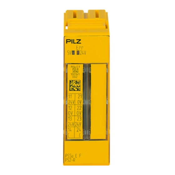
Page 8: Front View
2D code 3: Labelling strip for the terminal configuration on the base module 4: Name of electronic module 5: Connection level 1 6: Connection level 2 7: Connection level 3 8: Connection level 4 Operating Manual PSSu E F PS2(-T)(-R) 1002237-EN-05... - Page 9 10: Round connection holes (connection levels 1, 2, 3 and 4) for connecting the signal lines 11: Mounting slot for colour marker to label the connection level (connection levels 1, 2, 3 and 4) Operating Manual PSSu E F PS2(-T)(-R) 1002237-EN-05...
-
Page 10: Safety
The module may be used in system environment B (automation system PSS 4000). The modules PSSu E F PS2 and PSSu E F PS2-T may be used as a safety components in accordance with the Lifts Directive 95/16/EC in accordance with the requirements of EN 81-1/2:1998+A3:2009, EN 81-20:2015, EN 81-50:2015, EN 81-22:2014 and... -
Page 11: Safety Regulations
The PSSu E F PS2 module may be used in conjunction with the following base modules: PSSu BS-R 2/8 S PSSu BS-R 2/8 C The PSSu E F PS2-T and PSSu E F PS2-R modules may be used in conjunction with the following base modules: PSSu BS-R 2/8 S-T... -
Page 12: Function Description
Supply groups to be formed The relevant base module interrupts the connection to the incoming (left-hand) peri- phery supply and C-rail on the module bus. Each supply group requires its own supply module. Operating Manual PSSu E F PS2(-T)(-R) 1002237-EN-05... -
Page 13: Current Load Capacity
If the current load is higher, the C-rail must use a different supply to prevent overload. Please refer to the derating diagram. PSSu E F PS2: Derating diagram for periphery supply and C-rail: Temperature T depend- ent on load current I T (°C) -
Page 14: Integrated Protection Mechanisms
Function description PSSu E F PS2(-T)(-R): Derating diagram for periphery supply and C-rail: Temperature T dependent on load current I T [°C] 10 I [A] 4.2.2 Integrated protection mechanisms The module has the following protection mechanisms: Infeed for module supply –... -
Page 15: Installation
5.1.1 Dimensions 25,2 mm 8,1 mm 52,1 mm (0.992") (0.319") (2.051") 25,2 mm 72,7 mm (0.992") (2.862") Operating Manual PSSu E F PS2(-T)(-R) 1002237-EN-05... -
Page 16: Installing The Base Module
Push the base module back [2] until you hear it lock into position. On the mounting rail, slide the base module to the left until you hear the two lateral mounting hooks on the adjacent module lock into position [3]. Schematic representation: Operating Manual PSSu E F PS2(-T)(-R) 1002237-EN-05... -
Page 17: Inserting And Removing An Electronic Module
This is how the base module is coded. The mechanics of the electronic modules are designed for 50 plug in/out cycles. Operating Manual PSSu E F PS2(-T)(-R) 1002237-EN-05... -
Page 18: Inserting An Electronic Module
Installation 5.3.1 Inserting an electronic module Procedure: The electronic module must audibly lock into position [1]. Mark the electronic module using the labelling strips [2]. Schematic representation: Operating Manual PSSu E F PS2(-T)(-R) 1002237-EN-05... -
Page 19: Removing An Electronic Module
– The substitute values are used for the modules' FS outputs, with Valid Bits = FALSE. CAUTION! Sparking can cause interference and errors! Only change the module when the load is switched off! Operating Manual PSSu E F PS2(-T)(-R) 1002237-EN-05... -
Page 20: Wiring
Insert the stripped cable into the round fixing hole [2], as far as it will go. – Tighten up the screw on the screw terminal. – Check that the cable is firmly seated. Operating Manual PSSu E F PS2(-T)(-R) 1002237-EN-05... - Page 21 Inputs/outputs on the counter modules: 1.5 mm (AWG16) – Analogue inputs/outputs: 1.5 mm (AWG16) – Communication cables: 1.5 mm (AWG16) – Test pulse outputs: 1.5 mm (AWG16) – Power supply: 2.5 mm (AWG12) – Functional earth: 2.5 mm (AWG12) Operating Manual PSSu E F PS2(-T)(-R) 1002237-EN-05...
-
Page 22: Terminal Configuration
(12-22 linked within the base module) 13 -23: +24 V periphery sup- ply, interrupted to the left (13-23 linked within the base module) 14-24 C-rail supply, interrupted to the left (14-24 linked within the base module) Operating Manual PSSu E F PS2(-T)(-R) 1002237-EN-05... - Page 23 [ . . . ] Module Supply Module Supply (24 V DC) (24 V DC) 24 V DC 24 V DC Refresh of the Periphery Supply Periphery Supply (24 V DC) C-rail supply (24 V DC) Operating Manual PSSu E F PS2(-T)(-R) 1002237-EN-05...
-
Page 24: Connecting The Module
Module Supply Periphery Supply PSSu E F PS2 - PSSu BS-R 2/8S(-T) - PSSu BS-R 2/8C(-T) Connect to the C-rail supply Connect to the 0 V supply and earth at a single point Operating Manual PSSu E F PS2(-T)(-R) 1002237-EN-05... -
Page 25: Operation
LED flashes LED off 7.2.1 Display elements for module diagnostics The module has an LED for displaying module errors ("Err" LED). Meaning Designation Colour Status - - - No error Module error 11 21 Operating Manual PSSu E F PS2(-T)(-R) 1002237-EN-05... -
Page 26: Display Elements For The Status Of The Module Supply And Periphery Supply
24 V - - - Error in the supply voltage for periphery supply No supply voltage for periphery sup- Green Supply voltage for periphery supply is er- ror-free Operating Manual PSSu E F PS2(-T)(-R) 1002237-EN-05... - Page 27 Current load capacity 10 A 10 A 10 A at UB Rated surge voltage 3050 V 3050 V – Potential isolation between module supply and periphery supply 3050 V 3050 V 3050 V Operating Manual PSSu E F PS2(-T)(-R) 1002237-EN-05...
- Page 28 -40 ... +70 °C In accordance with the EN 50125-3 standard – – Temperature range – – -40 ... +70 °C Storage temperature -25 - 70 °C -40 - 70 °C Temperature range – Operating Manual PSSu E F PS2(-T)(-R) 1002237-EN-05...
- Page 29 Supply interruptions In accordance with the standard – – EN 50155 Class – – S2, C1, C2 Airgap creepage In accordance with the standard EN 60664-1 EN 60664-1 EN 50124-1 Overvoltage category Pollution degree Operating Manual PSSu E F PS2(-T)(-R) 1002237-EN-05...
- Page 30 25,2 mm Depth 60,2 mm 60,2 mm 60,2 mm Weight 49 g 51 g 53 g Mechanical coding Type Colour Yellow Yellow Yellow Where standards are undated, the 2015-03 latest editions shall apply. Operating Manual PSSu E F PS2(-T)(-R) 1002237-EN-05...
- Page 31 Base module with cage clamp terminals, for use only to refresh 312 655 the voltage and form supply groups PSSu BS-R 2/8 C- Base module with cage clamp terminals, for use only to refresh 314 655 the voltage and form supply groups, T-type Operating Manual PSSu E F PS2(-T)(-R) 1002237-EN-05...
- Page 32 Front cover Support Technical support is available from Pilz round the clock. Americas Australia Scandinavia Brazil +61 3 95600621 +45 74436332 +55 11 97569-2804 Spain Canada Europe +34 938497433 +1 888-315-PILZ (315-7459) Austria Switzerland +41 62 88979-30 Mexico +43 1 7986263-0...
Need help?
Do you have a question about the PSSu E F PS2 and is the answer not in the manual?
Questions and answers