
Related Manuals for Pilz PSSu E F 4DO 0.5


Summary of Contents for Pilz PSSu E F 4DO 0.5
- Page 1 PSSu E F 4DO 0.5(-T)(-R) Decentralised system PSSuniversal I/O Operating Manual-21316-EN-08...
- Page 2 Preface This document is a translation of the original document. All rights to this documentation are reserved by Pilz GmbH & Co. KG. Copies may be made for internal purposes. Suggestions and comments for improving this documentation will be gratefully received.
-
Page 3: Table Of Contents
Changing an electronic module during operation Section 6 Wiring General wiring guidelines 6.1.1 Mechanical connection of the base modules Terminal configuration Connecting the module Function test during commissioning Section 7 Operation Messages Operating Manual PSSu E F 4DO 0.5(-T)(-R) 21316-EN-08... - Page 4 Display elements for module diagnostics 7.2.2 Display elements for an output's FS enable 7.2.3 Display elements for output status Section 8 Technical details Safety characteristic data Section 9 Order reference Product Accessories Operating Manual PSSu E F 4DO 0.5(-T)(-R) 21316-EN-08...
-
Page 5: Operating Manual Pssu E F 4Do 0.5(-T)(-R)
Introduction Validity of documentation This documentation is valid for the product types PSSu E F 4DO 0.5, PSSu E F 4DO 0.5-T and PSSu E F 4DO 0.5-R. It is valid until new documentation is published. This operating manual explains the function and operation, describes the installation and provides guidelines on how to connect the product. -
Page 6: Definition Of Symbols
It also highlights areas within the text that are of particular import- ance. INFORMATION This gives advice on applications and provides information on special fea- tures. Operating Manual PSSu E F 4DO 0.5(-T)(-R) 21316-EN-08... -
Page 7: Overview
FS enable per output – Module error For failsafe applications in system environment A and B T-type: PSSu E F 4DO 0.5-T: for increased environmental requirements R-type: PSSu E F 4DO 0.5-R: for railway applications Operating Manual PSSu E F 4DO 0.5(-T)(-R) 21316-EN-08... -
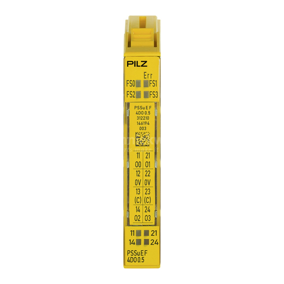
Page 8: Front View
Serial number – Hardware version number – 2D code 3: Labelling strip for the terminal configuration on the base module 4: Status LEDs 5: Name of electronic module 6: Connection level 1 Operating Manual PSSu E F 4DO 0.5(-T)(-R) 21316-EN-08... - Page 9 11: Round connection holes (connection levels 1, 2, 3 and 4) for connecting the signal lines 12: Mounting slot for colour marker to label the connection level (connection levels 1, 2, 3 and 4) Operating Manual PSSu E F 4DO 0.5(-T)(-R) 21316-EN-08...
-
Page 10: Safety
The module meets the requirements of EN IEC 61508 up to SIL 3. The modules PSSu E F 4DO 0.5 and PSSu E F 4DO 0.5-T may be used as a safety com- ponents in accordance with the Lifts Directive 95/16/EC in accordance with the require- ments of EN 81-1/2:1998+A3:2009, EN 81-20:2015, EN 81-50:2015, EN 81-22:2014 and... -
Page 11: Safety Regulations
PSSu BP 1/12 C PSSu BP-C1 1/12 S PSSu BP-C1 1/12 C The PSSu E F 4DO 0.5-T and PSSu E F 4DO 0.5-R modules may be used in conjunction with the following base modules: PSSu BP 1/8 S-T PSSu BP 1/8 C-T... -
Page 12: Warranty And Liability
In safety-related applications, please comply with the mission time T in the safety-re- lated characteristic data. When decommissioning, please comply with local regulations regarding the disposal of electronic devices (e.g. Electrical and Electronic Equipment Act). Operating Manual PSSu E F 4DO 0.5(-T)(-R) 21316-EN-08... -
Page 13: Function Description
Operation with electronic contactors has not been tested and may lead to errors. Please contact our Customer Support team if you are using electronic contactors. Operating Manual PSSu E F 4DO 0.5(-T)(-R) 21316-EN-08... - Page 14 WARNING! When wiring an output with capacitance it is essential to note the pulse dur- ation, repetition period and scan time of the power-up test, otherwise the load may switch on unintentionally. Operating Manual PSSu E F 4DO 0.5(-T)(-R) 21316-EN-08...
- Page 15 Cycle time of on test when test is repeated (ca. 4 ms) Cycle time of on test in normal circumstances (approx. 5 min.) Characteristic: Output capacitance C dependent on load current I C [µF] I [mA] 250 300 Operating Manual PSSu E F 4DO 0.5(-T)(-R) 21316-EN-08...
-
Page 16: Integrated Protection Mechanisms
Function description Derating diagram (PSSu E F 4DO 0.5(-T)(-R)): Permitted ambient temperature T depend- ent on load current I T [°C] I [A] 0,05 0,10 0,15 0,20 0,25 0,30 0,35 0,40 0,45 0,50 4.2.2 Integrated protection mechanisms When the PSSu E F PS1(-T) or PSSu E F PS2(-T)(-R) is used to supply the system, the module supply is buffered for 20 ms if the supply voltage is interrupted. -
Page 17: Configuration
PSSu assignment in system environment B Data access is via pre-defined I/O data types: I/O data name I/O data type I/O data element Meaning O0(11), O1(21), O2(14), FS_O_DO Data: SAFEBOOL Output data O0 ... O3 O3(24) Operating Manual PSSu E F 4DO 0.5(-T)(-R) 21316-EN-08... -
Page 18: Installation
5.1.1 Dimensions Base modules with four connection levels: 12,6 mm 8,1 mm 52,1 mm (0.496") (0.319") (2.051") 12,6 mm 72,6 mm (0.496") (2.858") Operating Manual PSSu E F 4DO 0.5(-T)(-R) 21316-EN-08... -
Page 19: Installing The Base Module
Push the base module back [2] until you hear it lock into position. On the mounting rail, slide the base module to the left until you hear the two lateral mounting hooks on the adjacent module lock into position [3]. Operating Manual PSSu E F 4DO 0.5(-T)(-R) 21316-EN-08... -
Page 20: Inserting And Removing An Electronic Module
This is how the base module is coded. The mechanics of the electronic modules are designed for 50 plug in/out cycles. Operating Manual PSSu E F 4DO 0.5(-T)(-R) 21316-EN-08... -
Page 21: Inserting An Electronic Module
Installation 5.3.1 Inserting an electronic module Procedure: The electronic module must audibly lock into position [1]. Mark the electronic module using the labelling strips [2]. Schematic representation: Operating Manual PSSu E F 4DO 0.5(-T)(-R) 21316-EN-08... -
Page 22: Removing An Electronic Module
The substitute values are used for the modules' FS outputs, with Valid Bits = FALSE. CAUTION! Sparking can cause interference and errors! Only change the module when the load is switched off! Operating Manual PSSu E F 4DO 0.5(-T)(-R) 21316-EN-08... -
Page 23: Wiring
Insert the screwdriver [4] into the square hole [1]. – Insert the stripped cable into the round fixing hole [2], as far as it will go [5]. – Pull out the screwdriver [6]. Operating Manual PSSu E F 4DO 0.5(-T)(-R) 21316-EN-08... - Page 24 To crimp the ferrules you can use crimp pliers (crimp form A or C) conforming to EN 60947-1, such as the PZ 1.5 or PZ 6.5 from Weidmüller, for example. Operating Manual PSSu E F 4DO 0.5(-T)(-R) 21316-EN-08...
- Page 25 Wiring – Maximum torque setting: 0.8 Nm Use copper wiring. Operating Manual PSSu E F 4DO 0.5(-T)(-R) 21316-EN-08...
-
Page 26: Terminal Configuration
PSSu BP-C 1/8 C PSSu BP-C 1/8 C-T 12-22: 0 V periphery supply (12-22 linked within the base module) 13-23: C-rail supply (13-23 linked within the base module) 14: Output O2 24: Output O3 Operating Manual PSSu E F 4DO 0.5(-T)(-R) 21316-EN-08... - Page 27 (13-23-16-26 linked within the base module) 14: Output O2 24: Output O3 15-25: 0 V periphery supply (15-25 linked within the base module) 16-26: C-rail supply (13-23-16-26 linked within the base module) Operating Manual PSSu E F 4DO 0.5(-T)(-R) 21316-EN-08...
-
Page 28: Connecting The Module
Wiring Connecting the module Output circuit Without C-rail With C-rail Single-channel actuator Single-channel actuator Operating Manual PSSu E F 4DO 0.5(-T)(-R) 21316-EN-08... -
Page 29: Function Test During Commissioning
INFORMATION The short circuit test must be performed on the load and not on the output terminal. Operating Manual PSSu E F 4DO 0.5(-T)(-R) 21316-EN-08... -
Page 30: Operation
If the temperature drops back below the threshold value, the module sends an all-clear. Too hot: If a module's temperature exceeds a further threshold value, the module sends an error message to the head module and triggers an I/O-Group stop. Operating Manual PSSu E F 4DO 0.5(-T)(-R) 21316-EN-08... -
Page 31: Display Elements
O1 - - - No FS enable for output O2 Yellow FS enable for output O2 - - - No FS enable for output O3 Yellow FS enable for output O3 Operating Manual PSSu E F 4DO 0.5(-T)(-R) 21316-EN-08... -
Page 32: Display Elements For Output Status
12 22 - - - 0 signal 13 23 (Output 14 24 Green 1 signal - - - 0 signal (Output Green 1 signal - - - 0 signal (Output Green 1 signal Operating Manual PSSu E F 4DO 0.5(-T)(-R) 21316-EN-08... -
Page 33: Technical Details
Typ. output current at "1" signal and rated voltage of semiconductor output 0,5 A 0,5 A 0,5 A Permitted current range 0,000 - 0,620 A 0,000 - 0,620 A 0,000 - 0,620 A Operating Manual PSSu E F 4DO 0.5(-T)(-R) 21316-EN-08... - Page 34 Temperature range – – -40 ... +70 °C Storage temperature In accordance with the standard EN 60068-2-1/-2 EN 60068-2-1/-2 EN 60068-2-1/-2 Temperature range -25 - 70 °C -40 - 70 °C – Operating Manual PSSu E F 4DO 0.5(-T)(-R) 21316-EN-08...
- Page 35 In accordance with the standard – – EN 50155 Class – – S2, C1, C2 Airgap creepage In accordance with the standard EN 60664-1 EN 60664-1 EN 50124-1 Overvoltage category Pollution degree Operating Manual PSSu E F 4DO 0.5(-T)(-R) 21316-EN-08...
-
Page 36: Safety Characteristic Data
PFH and PFD will need to be doubled when a safety function is calculated. All the units used within a safety function must be considered when calculating the safety characteristic data. Operating Manual PSSu E F 4DO 0.5(-T)(-R) 21316-EN-08... - Page 37 A safety function's SIL/PL values are not identical to the SIL/PL values of the units that are used and may be different. We recommend that you use the PAScal software tool to calculate the safety function's SIL/PL values. Operating Manual PSSu E F 4DO 0.5(-T)(-R) 21316-EN-08...
-
Page 38: Order Reference
PSSu BP-C1 1/12 S-T Base module with C-rail and screw terminals, T-type 314 622 PSSu BP-C1 1/12 C Base module with C-rail and cage clamp terminals 312 623 PSSu BP-C1 1/12 C- Base module with C-rail and cage clamp terminals, T-type 314 623 Operating Manual PSSu E F 4DO 0.5(-T)(-R) 21316-EN-08... - Page 39 Front cover Support Technical support is available from Pilz round the clock. Americas Australia Scandinavia Brazil +61 3 95600621 +45 74436332 +55 11 97569-2804 Spain Canada Europe +34 938497433 +1 888-315-PILZ (315-7459) Austria Switzerland Mexico +43 1 7986263-0 +41 62 88979-30...
Need help?
Do you have a question about the PSSu E F 4DO 0.5 and is the answer not in the manual?
Questions and answers