
Related Manuals for Pilz PSSu E F PS1-T


Summary of Contents for Pilz PSSu E F PS1-T
- Page 1 PSSu E F PS1(-T) Decentralised system PSSuniversal I/O Operating Manual-21298-EN-06...
- Page 2 Preface This document is a translation of the original document. All rights to this documentation are reserved by Pilz GmbH & Co. KG. Copies may be made for internal purposes. Suggestions and comments for improving this documentation will be gratefully received.
-
Page 3: Table Of Contents
Contents Section 1 Introduction Validity of documentation 1.1.1 Retaining the documentation Definition of symbols Section 2 Overview Module structure Module features Front view Section 3 Safety Intended use Safety regulations 3.2.1 Use of qualified personnel 3.2.2 Warranty and liability 3.2.3 Disposal Section 4 Function description... - Page 4 Contents 7.2.2 Display elements for the status of the module supply and periphery supply 29 Status byte Section 8 Technical details Section 9 Order reference Product Accessories Operating Manual PSSu E F PS1(-T) 21298-EN-06...
-
Page 5: Operating Manual Pssu E F Ps1(-T)
Introduction Validity of documentation This documentation is valid for the products PSSu E F PS1 and PSSu E F PS1-T. It is valid until new documentation is published. The module PSSu E F PS1-T is suitable for use where there are increased environmental requirements (see Technical Details). - Page 6 Introduction INFORMATION This gives advice on applications and provides information on special fea- tures. Operating Manual PSSu E F PS1(-T) 21298-EN-06...
-
Page 7: Overview
Separate infeed for module supply Infeed for C-rail supply LEDs for: – Module supply – Periphery supply – Module error Application range depends on the base module T-type: PSSu E F PS1-T: for increased environmental requirements Operating Manual PSSu E F PS1(-T) 21298-EN-06... -
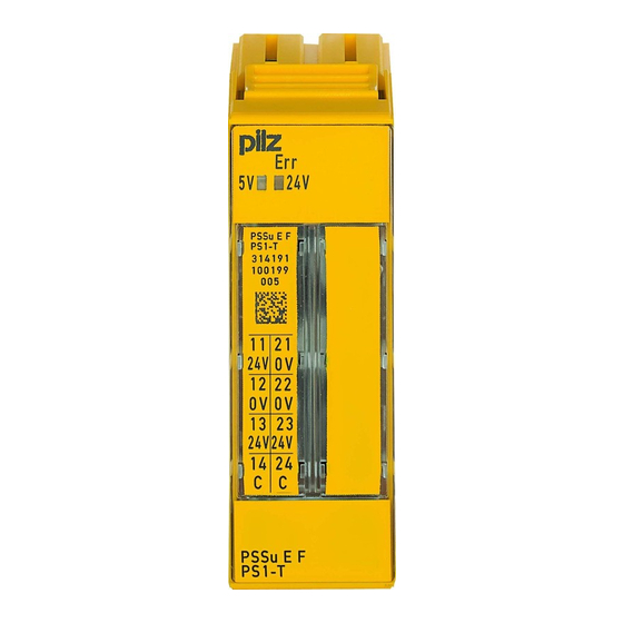
Page 8: Front View
Overview Front view PSSu E F 312191 000000 11 21 13 23 24V 24V PSSu E F Key: A: Electronic module B: Base module 1: LED for module diagnostics 2: Labelling strip with: – Name of electronic module – Order number –... - Page 9 Overview 9: Square mounting holes (connection levels 1, 2, 3 and 4) – With screw to loosen/tighten the screw terminal on base modules with screw termin- – With mechanism to operate the cage clamp on base modules with cage clamp ter- minals 10: Round connection holes (connection levels 1, 2, 3 and 4) for connecting the signal lines...
-
Page 10: Safety
PSSu BS-R 2/8 S PSSu BS 2/8 C PSSu BS-R 2/8 C The module PSSu E F PS1-T may be used in conjunction with the following base modules: PSSu BS 2/8 S-T PSSu BS-R 2/8 S-T PSSu BS 2/8 C-T... -
Page 11: Safety Regulations
Safety Safety regulations 3.2.1 Use of qualified personnel The products may only be assembled, installed, programmed, commissioned, operated, maintained and decommissioned by competent persons. A competent person is a qualified and knowledgeable person who, because of their train- ing, experience and current professional activity, has the specialist knowledge required. To be able to inspect, assess and operate devices, systems and machines, the person has to be informed of the state of the art and the applicable national, European and international laws, directives and standards. -
Page 12: Function Description
Function description Function description Block diagram 12 22 13 23 11 21 Periphery Supply + 24 V DC Module Supply + 5 V DC Power Power Module Periphery Data Supply Supply (FS) (C-Rail) 14 24 Module features 4.2.1 Supply voltage The product provides the module supply and periphery supply for the modules on the mod- ule bus: Module supply... -
Page 13: Current Load Capacity
Function description 4.2.1.1 Current load capacity Ensure you comply with the current load capacity of the module and periphery supply (see "Technical Details"). If the current load is higher, an additional supply voltage module is re- quired to refresh the module supply and periphery supply. Module supply The current load is the total current consumption of all the electronic and compact mod- ules. - Page 14 Function description PSSu E F PS1-T: Derating diagram for infeed for periphery supply: Permitted ambient tem- perature T dependent on load current I T [°C] 10 I [A] PSSu E F PS1-T: Derating diagram for infeed for module supply: Permitted ambient tem- perature T dependent on load current I T [°C]...
-
Page 15: Integrated Protection Mechanisms
Function description 4.2.2 Integrated protection mechanisms The module has the following protection mechanisms: Infeed for module supply – Polarity protection – Voltage monitoring – Transient voltage limitation Module supply – Short circuit-proof Periphery supply – Voltage monitoring (exceeding upper/lower limit) The module registers the following errors: Start-up error Configuration error... -
Page 16: Fs Error Behaviour
Function description INFORMATION Further information on the structure and contents of the status byte can be found under “Operation”. 4.3.3 FS error behaviour In the case of a safety-related error on an FS output, all FS outputs in the affected I/O- Group (SafetyBUS p) are shut down. -
Page 17: Installation
Installation Installation General installation guidelines Please refer also to the PSSuniversal Installation Manual. NOTICE Damage due to electrostatic discharge! Electrostatic discharge can damage components. Ensure against discharge before touching the product, e.g. by touching an earthed, conductive sur- face or by wearing an earthed armband. 5.1.1 Dimensions 25,2 mm... -
Page 18: Installing The Base Module
Installation Installing the base module Prerequisite: The head module must be installed. If the head module does not have an integrated power supply, a supply voltage module must be installed to the right of the head module. Please note: For mechanical reasons it is not possible to mix base modules with screw terminals and base modules with cage clamp terminals. -
Page 19: Inserting And Removing An Electronic Module
Installation Inserting and removing an electronic module Please note: Only insert on to base modules that are already installed. Preferably these base modules should be ready wired. Electronic modules with outputs may only be inserted and removed when the load is switched off. -
Page 20: Inserting An Electronic Module
Installation 5.3.1 Inserting an electronic module Procedure: The electronic module must audibly lock into position [1]. Mark the electronic module using the labelling strips [2]. Schematic representation: Operating Manual PSSu E F PS1(-T) 21298-EN-06... -
Page 21: Removing An Electronic Module
Installation 5.3.2 Removing an electronic module Procedure: Press the locking mechanisms [1] together simultaneously. Pull out the electronic module [2]. Schematic representation: 5.3.3 Changing an electronic module during operation It is possible to change an electronic module during operation. The configuration data is re- tained when a module is changed. -
Page 22: Wiring
Wiring Wiring General wiring guidelines Please note: The requirements of the supply voltages can be found in the chapter entitled "Technical Details". Protective separation must be ensured for the external power supplies that generate the supply voltages. Failure to do so could result in electric shock. The external power supplies must comply with the current applicable standard EN 60950-1, EN 61140, EN 50178 or EN 61558-1. - Page 23 Wiring Base module with cage clamp terminals: – Insert the screwdriver [4] into the square hole [1]. – Insert the stripped cable into the round fixing hole [2], as far as it will go [5]. – Pull out the screwdriver [6]. –...
-
Page 24: Terminal Configuration
Wiring On base modules with screw terminals: – If you use a multi-strand cable to connect the I/Os, it is recommended that you use ferrules conforming to Parts 1 and 2 of DIN 46228, 0.14 ... 1.5 mm , Form A or C, although this is not essential. - Page 25 Wiring [ . . . ] 5 V DC Infeed for Module bus Module Supply (24 V DC) [ . . . ] 24 V DC Periphery Supply (24 V DC) C-rail Supply For use as a supply module to refresh the module supply and periphery supply For use as a supply module to form supply groups –...
- Page 26 Wiring Base module Terminal configuration Screw terminals: 11: +24 V infeed for module PSSu BS-R 2/8 S supply, PSSu BS-R 2/8 S-T interrupted to the left Cage clamp terminals: 21: 0 V infeed for module PSSu BS-R 2/8 C supply PSSu BS-R 2/8 C-T 12 -22: 0 V periphery supply, interrupted to the left...
-
Page 27: Connecting The Module
0 V DC +24 V DC 0 V DC +24 V DC PSSu E F PS1/ PSSu E F PS1-T with - PSSu BS 2/8S(-T) - PSSu BS 2/8C(-T) - PSSu BS-R 2/8S(-T) - PSSu BS-R 2/8C(-T) Connect to the... -
Page 28: Operation
Operation Operation Messages A module error is displayed via the “Err” LED (see section entitled “Display elements”), sig- nalled to the head module and then entered in the head module's error stack or diagnostic log. The module can detect the following errors: Module error Explanation Remedy... -
Page 29: Display Elements For The Status Of The Module Supply And Periphery Supply
Operation 7.2.2 Display elements for the status of the module supply and periphery supply A status LED is assigned to both the module supply and periphery supply ("5 V" and "24 V" LEDs). Description Colour Status - - - No supply voltage or er- ror in the sup- ply voltage for... -
Page 30: Status Byte
Operation Status byte The first supply module after the head module can communicate a variety of status informa- tion to the ST-PII (see table below). The information is transmitted using the module's status byte. Read access (R) is configured for that purpose. Structure and contents of the status byte Bit number Signal SafetyBUS p in a STOP condition... -
Page 31: Technical Details
Technical details Technical details General 312191 314191 CE, EAC (Eurasian), KOSHA, CE, EAC (Eurasian), KOSHA, Approvals TÜV, cULus Listed TÜV, cULus Listed Application range Standard/failsafe Standard/failsafe 0800h 0800h Module's device code Application in system environment From FS firmware version, other head modules From ST firmware version, other head modules... - Page 32 Technical details Electrical data 312191 314191 Internal supply voltage (module supply) Output voltage int. system int. system Voltage Voltage tolerance -2 %/+3 % -2 %/+3 % Module's power consumption 0,12 W 0,12 W 3050 V 3050 V Potential isolation Current load capacity Buffer in the case of supply in- DIN V EN V 1954, EN61131-2, DIN V EN V 1954, EN61131-2,...
- Page 33 Technical details Environmental data 312191 314191 Shock stress In accordance with the standard EN 60068-2-27 EN 60068-2-27 Number of shocks Acceleration Duration 11 ms 11 ms In accordance with the standard EN 60068-2-27 EN 60068-2-27 1000 1000 Number of shocks Acceleration Duration 16 ms...
-
Page 34: Order Reference
Order reference Order reference Product Product type Features Order No. PSSu E F PS1 Electronic module, base type 312 191 PSSu E F PS1-T Electronic module, T-type 314 191 Accessories Base modules Product type Features Order No. PSSu BS 2/8 S... - Page 35 Front cover Support Technical support is available from Pilz round the clock. Americas Australia Scandinavia Brazil +61 3 95600621 +45 74436332 +55 11 97569-2804 Spain Canada Europe +34 938497433 +1 888-315-PILZ (315-7459) Austria Switzerland +41 62 88979-30 Mexico +43 1 7986263-0...
Need help?
Do you have a question about the PSSu E F PS1-T and is the answer not in the manual?
Questions and answers