Advertisement
Table of Contents
MODEL#L-GZ938PCO-B/L-GZ938PCO-B2
IMPORTANT: RETAIN FOR FUTURE REFERENCE. READ CAREFULLY.
Please check with your local governing authority / local municipal codes regarding
installation of structures before assembly.
Tools required (not included): Phillips screwdriver, 2 ladders, cordless drill, metric socket and carpenter's level.
WARNING:
Check to ensure all parts are present prior to assembly.
This unit is heavy! At least 2 adults are needed for safe assembly ---- Never assemble this alone!
Keep all children and pets away from assembly area. Children and pets should be supervised when they are in
the area of the gazebo construction.
Keep assembly area more than 1.8 m / 5.9 ft / 5.9 pi from any obstruction such as fence, garage, and house,
overhanging branches, laundry line or electrical wires.
Some parts may contain sharp edges. When assembling and using this product, basic safety precautions
should always be followed to reduce the risk of personal injury and damage to the product. Please read all
instructions before assembly and use.
For outdoor use only. Check all bolts for tightness before use and periodically check and tighten bolts as
necessary.
Assemble this unit on firm, level ground or hard surface only. Ensure the unit is level after final assembly.
Protect parts during assembly by laying them on a non-abrasive surface such as blankets or cardboard.
DO NOT REMOVE THE PROTECTIVE FILM ON THE POLYCARBONATE ROOF PANELS UNTIL
INSTALLATION. MAKE SURE TO PUT THE UV PROTECTED SIDE FACING UP. IT IS A VERY IMPORTANT
PROCEDURE, IF NOT FOLLOWED AS DESCRIBED. YOUR ROOF WILL NOT BE COVERED BY THE
GUARANTEE.
IMPORTANT
Please do not return this product to the store. For technical assistance or replacement parts call Sunjoy from 8:30
AM to 4:30 PM Eastern Time at the following: 1-866-578-0101 (English, French & Spanish in US) or e-mail:
service@ferro-works.com.
November 2015
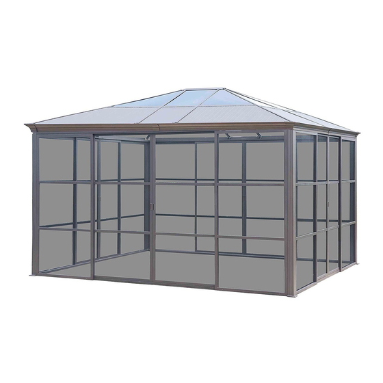
SCREEN ROOM
ITM./ART. 470260
ASSEMBLY INSTRUCTIONS
Advertisement
Table of Contents

Related Manuals for Sunjoy L-GZ938PCO-B


Summary of Contents for Sunjoy L-GZ938PCO-B
- Page 1 GUARANTEE. IMPORTANT Please do not return this product to the store. For technical assistance or replacement parts call Sunjoy from 8:30 AM to 4:30 PM Eastern Time at the following: 1-866-578-0101 (English, French & Spanish in US) or e-mail: service@ferro-works.com.
-
Page 2: Parts List
Parts List DESCRIPTION PART # LINE DRAWING OF PART Slide rail 1 (long, lower left) Slide rail 2 (long, lower right) Slide rail 3 (short, lower left) Slide rail 4 (short, lower right) Connector 1 Post Wall screen 1 (left) Wall screen 2 (right) Gutter 1 (long, left) Gutter 2 (long, right) - Page 3 DESCRIPTION PART # LINE DRAWING OF PART Rail track 1 (long, upper left) Rail track 2 (long, upper right) Rail track 3 (short, upper left) Rail track 4 (short, upper right) Rail block slice Connector 3 Connector 4 Bracket 1 (long, left) Bracket 2 (long, right) Bracket 3 (short, left) Bracket 4 (short, right)
-
Page 4: Line Drawing
DESCRIPTION PART # LINE DRAWING OF PART Roof Beam 1 (outside, lower left corner) Beam 2 (outside, lower right corner) Beam 3 (outside, lower left middle) Beam 4 (outside, lower right middle) Decorative groove connector Bar 3 (short, Left) Bar 4 (short, right) Bar 5 (short, middle) Connector 6 (left) Connector 7 (right) - Page 5 Fig.1: Insert the side with label “Out” of Wall screen 1 (left) (C1) into the bottom slot of Post (B). (Note: Label “Out” should be on outside). Repeat this step for the 3 remaining Wall screens 1 (left) (C1) and all Wall screens 2 (right) (C2). Fig.2: Connect Slide rail 1 (long, lower left) (A1) and Slide rail 2 (long, lower right) (A2) to connector 1 (A5) using M6 x 15 mm bolts (AA) and M6 washers (BB).
- Page 6 Fig.7-1: Attach Connector 3 (J1) to assembled Gutter 3 (short, left) (D3) and Gutter 4 (short, right) (D4) using M6 x 15 mm bolts (AA) and M6 washers (BB). Fig.7-2: Attach Connector 3 (J1) to assembled Gutter1 (long, left) (D1) and Gutter 2 (long, right) (D2) using M6 x 15 mm bolts (AA) and M6 washers (BB).
- Page 7 Fig.12: Attach the bottom of Bar 2 (middle) (M2) to Connector 3 (J1) using M6 x 15 mm bolts (AA) and M6 washers (BB). Fig.13: Attach Roof (P) to Connector 5 (roof) (L) using M6 x 15 mm bolts (AA) and M6 washers (BB). Secure Hook (L) to Connector 5 (roof) (L). Fig.14: Attach Bar 5 (short, middle) (S3) and Bar 3 (short, left) (S1) to Bar 2 (middle) (M2) using M6 x 25 mm bolts (CC) and M6 washers (BB).
- Page 8 Fig.16: Slide PC panel 1 (left) (O1) into the top section created by Bar 1 (corner) (M1) and Bar 2 (middle) (M2). Repeat this step for PC panel 2 (right) (O2) and PC panel 3 (middle) (O3). Repeat for opposite side. Once the polycarbonate panels are installed, remove the protective film. Fig.17: Insert Connector 6 (left) (T1) into the slot created by Bar 1 (corner) (M1) and Bar 2 (middle) (M2).
- Page 9 Hardware Pack for Step 4 PART # DESCRIPTION LINE DRAWING M6 x 15mm bolt 32 PCS M6 washer 32 PCS M5 x 15 mm bolt 32 PCS Φ8 x 260 stake 12 PCS Fig.25: Attach Wheels (H) to Movable door 1 (long, left) (F1), Movable door 2 (long, right) (F2), Movable door 3 (short, left) (G1) and Movable door 4 (short, right) (G2) using M5 x 15 mm bolts (GG).
-
Page 10: Care Instructions
Fig.29: Attach Rail track 1 (long, upper left) (I1) to Movable door 1 (long, left) (F1) through Wheel (H) as per above fig. Repeat this step for Rail track 3 (short, upper left) (I3) to Movable door 3 (short, left) (G1). (Note: The door with IN label should face inside) Fig.30: Put the wheel at the bottom of Movable door 1 (long, left) (F1) into Slide rail 1 (long, lower left) (A1).
Need help?
Do you have a question about the L-GZ938PCO-B and is the answer not in the manual?
Questions and answers
Can I get screen room replacement PC panels for model #L-GZ938PCO-B/L-GZ938PCO-B2 from you?
The document does not provide specific information about where to find replacement PC panels for the Sunjoy model L-GZ938PCO-B. However, it includes a contact for support: you can call 1-866-578-0101 or email service@ferro-works.com for assistance.
This answer is automatically generated