SUTO S120 Instruction And Operation Manual
Oil vapor monitor
Hide thumbs
Also See for S120:
- Instruction and operation manual (32 pages) ,
- Instruction and operation manual (36 pages) ,
- Instruction and operation manual (44 pages)
Table of Contents
Advertisement
Quick Links
Advertisement
Table of Contents

Related Manuals for SUTO S120


Summary of Contents for SUTO S120
- Page 1 English Instruction and operation manual S120 Oil Vapor Monitor...
- Page 2 The device is designed exclusively for the described application. SUTO offers no guarantee for the suitability for any other purpose. SUTO is also not liable for consequential damage resulting from the delivery, capability or use of this device.
-
Page 3: Table Of Contents
9.1.3 Status bar..............22 9.2 Main menus................23 9.3 Sensor settings ..............24 9.3.1 Basic setting..............24 9.3.2 Analog output ..............25 9.3.3 Modbus/RTU settings............25 9.3.4 Modbus/TCP settings............26 9.3.5 Alarm settings...............26 9.3.6 Status................26 9.4 Logger settings..............27 9.5 Files...................28 9.6 Service info ...............28 9.7 System settings ..............29 S120... - Page 4 10.1 LED indicators..............30 10.2 Error indications..............31 11 Signal outputs.................32 11.1 Analog output ..............32 11.2 Digital output ..............32 11.3 Alarm output ..............33 12 Optional accessories..............35 12.1 Sensor display..............35 12.2 Service kit ...............35 13 Calibration................35 14 Maintenance................35 15 Disposal or waste..............35 16 Warranty................36 S120...
-
Page 5: Safety Instructions
• Consider all regulations for electrical installations. • The system must be disconnected from any power supply during maintenance work. • Any electrical work on the system is only allowed by authorized qualified personal. S120... - Page 6 • Please make sure that the storage temperature of the device is between -20 ... +50°C. • Avoid direct UV and solar radiation during storage. • For the storage the humidity must be <90%, no condensation. S120...
-
Page 7: Registered Trademarks
2 Registered trademarks 2 Registered trademarks SUTO ® Registered trademark of SUTO iTEC MODBUS ® Registered trademark of the Modbus Organization, Hopkinton, USA HART ® Registered trademark of the HART Communication Foundation, Austin, USA Android™, Trademarks of Google LLC Google Play... -
Page 8: Application
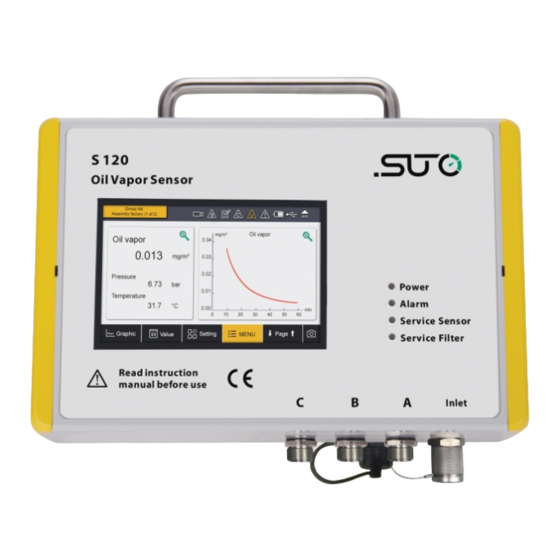
3 Application 3 Application The S120 Oil Vapor Monitor is designed to monitor oil contents and dew point (option) in compressed air and gases within the permissible operating parameters. These parameters can be found in the technical data section. The S120 is mainly used in compressed air systems in industrial environment. -
Page 9: Technical Data
Gas humidity < 40% rel. humidity, no condensation Operating pressure 3 ... 15 bar(g) (higher pressure on request) Low pressure (optional) 0.5 ... 2 bar(g) Housing material PC, Al alloy Protection class IP65 Dimensions See dimensional drawing on page 11. S120... -
Page 10: Electrical Data
5.3 Electrical data Power supply 24 VDC ± 5%, 10 W 5.4 Output signals Analog output 4 ... 20 mA Alarm output Relay, NO, 40 VDC, 0.2 A Digital interface RS-485, Modbus/RTU, Ethernet, Modbus/TCP, USB (available for display version) S120... -
Page 11: Dimensional Drawing
6 Dimensional drawing 6 Dimensional drawing S120... -
Page 12: Installation
This allows an easy installation at a wall. • S120-P for portable use. The portable version comes in a transport case. 7.2 Wall mounting instructions The device can be mounted on the wall using the supplied brackets. - Page 13 7 Installation Method 1. Method 2. S120...
-
Page 14: Installation Procedure
7.3.1 Installation requirements Please consider the following recommendations for a successful measurement result: • All components from the sampling point to the S120 must be oil and grease free. • Ambient and gas temperature must be within the specified ranges... - Page 15 Before you connect the device to your point of measurement, make sure that there is no rough contamination like water/oil drops or heavy dust. This may damage the sensor units. For this please use the purge filter test kit. S120...
-
Page 16: Installation Steps
7.3.2 Installation steps The following steps explain the procedure of an appropriate installation. Most importantly, before you connect S120 to the compressed air, purge air out from the measuring point to remove any residual contamination using the purge filter test kit. -
Page 17: Electrical Connection
Through this connector, the S120 connects to the TCP/IP network over the Modbus/TCP protocol. 7.4.3 M12 connectors The 3 M12 connectors are used to connect to display units from SUTO or the third-party displays and control units. Also, the S120 is powered through these connectors. - Page 18 7 Installation Color S120 S330/S331 S320 code Signal Terminal Terminal brown A.2 / B.2 white A.3 / B.3 blue black grey brown brown A.2 / B.2 white A.3 / B.3 blue black grey brown S120...
- Page 19 7 Installation S120 without display - M12 pin assignment Connector Pin 1 Pin 2 Pin 3 Pin 4 Pin 5 Relay Relay Color Brown White Blue Black Gray S120 with display - M12 pin assignment Connector Pin 1 Pin 2...
-
Page 20: Configuration
8.2 External display device See the S330/S331 Instruction Manual. 8.3 Service kit Please ensure that S120 or the service kit is connected with the power supply because the USB port cannot supply enough power for both of them. For more information, refer to the instruction manual of Service Kit. -
Page 21: Operations Using The Integrated Display
9 Operations using the integrated display 9 Operations using the integrated display If your S120 is equipped with the optional integrated display, you can configure the device by using the display. This chapter describes the usage of the display and provides instructions on how to configure the device . -
Page 22: Quick Buttons
Description of icons displayed in the status bar. USB stick connected System error Sensor connection has Sensor unit is not changed, not matching matching with with configuration configuration RTC backup battery Logger status status Sensor calibration is Alarm triggered expired S120... -
Page 23: Main Menus
The main menus and their functions are described below. Sensor settings To view and check the S120 settings. Logger To view and change S120 data logger settings. Files To check all recorded files and the memory status. Service info To view useful information in case of a service issue. -
Page 24: Sensor Settings
9 Operations using the integrated display 9.3 Sensor settings To configure sensor settings before starting measurement. After you changes settings, click “Save” to have the changes saved in the S120. 9.3.1 Basic setting Altitude To enter the Altitude. To accurately measure oil vapor, enter the altitude where the device is placed. -
Page 25: Analog Output
9 Operations using the integrated display 9.3.2 Analog output To configure the scaling of analog output. Whenever the output unit is changed, it is recommended to adjust the scaling of the analog output. 9.3.3 Modbus/RTU settings To change the Modbus/RTU settings. S120... -
Page 26: Modbus/Tcp Settings
9 Operations using the integrated display 9.3.4 Modbus/TCP settings To change the Modbus/TCP settings. 9.3.5 Alarm settings To configure the threshold of oil vapor that triggers the alarm. 9.3.6 Status To check the device status in case of a service issue. S120... -
Page 27: Logger Settings
Total recording channel number Sample rate Recording interval Status Logger status Recorded data can be downloaded to an USB memory drive on site (USB OTG Drive) or can be transferred to a PC using the supplied USB cable and the software S4A. S120... -
Page 28: Files
9 Operations using the integrated display 9.5 Files To view and manage all recorded measurement files and screenshots. To view the available memory. 9.6 Service info To view the contact information of the company that provides the service. S120... -
Page 29: System Settings
9 Operations using the integrated display 9.7 System settings To view and change S120 system-level settings. Password To set the password to protect some critical operations from unauthorized access. Back light To adjust brightening and dimming time out. Calibrate touch... -
Page 30: Troubleshooting
10 Troubleshooting 10 Troubleshooting This chapter describes how to troubleshoot S120 based on error indications such as LED indicators, relay status, and current output. 10.1 LED indicators Indicates the power status. Indicates the alarm status. Indicates whether the sensor need to be serviced. -
Page 31: Error Indications
10 Troubleshooting 10.2 Error indications This table lists the main error indications with S120 and the corresponding instructions to locate and fix errors. When the alarm LED is on, 1. Measure the current output and relay status. 2. Refer to the following table to proceed. -
Page 32: Signal Outputs
11 Signal outputs 11 Signal outputs 11.1 Analog output The S120 has an analog output range of 4 ... 20 mA. This output is scaled to: • 4 mA = 0.000 mg/m • 20 mA = 5.000 mg/m 11.2 Digital output... -
Page 33: Alarm Output
Sensor signal is too high Filter overdue 11.3 Alarm output The S120 has a relay alarm output. It is possible to monitor such as the oil vapor content and give an alarm at a particular threshold value. Alarm relay specifications: Rating: 40 VDC, 0.2 A... - Page 34 Alarm Situation Relay state S120 is powered off OPEN S120 is powered on / no alarm value is CLOSED reached S120 is powered on / alarm value is reached OPEN The advantage of the normally open relay is, that both critical situations can be detected, not only if the alarm value is reached, also if the device has power loss.
-
Page 35: Optional Accessories
The sensor display comes with a data logger that can store 100 million measurement values. 12.2 Service kit The service kit enables you to configure an S120 that is not equipped with the local display. For more information, see Service kit. -
Page 36: Warranty
The warranty does not cover any wear parts or consumables, therefore the UV lamp with limited lifetime as well as the internal filter are not covered by the warranty. SUTO iTEC GmbH SUTO iTEC (ASIA) Co., Ltd. Grißheimer Weg 21 Room 10, 6/F, Block B, Cambridge Plaza D-79423 Heitersheim 188 San Wan Road, Sheung Shui, N.T.
Need help?
Do you have a question about the S120 and is the answer not in the manual?
Questions and answers