Table of Contents
Advertisement
Quick Links
Advertisement
Table of Contents

Related Manuals for SUTO S110


Summary of Contents for SUTO S110
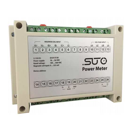
- Page 1 English Instruction and operation manual S110 Power Meter...
- Page 2 The device is destined exclusively for the described application. SUTO offers no guarantee for the suitability for any other purpose. SUTO is also not liable for consequential damage resulting from the delivery, capability or use of this device.
-
Page 3: Table Of Contents
9.2.4 Topology of Modbus/RTU Daisy-Chain.......17 10 Optional Extra Accessories............19 11 Maintenance................19 12 Disposal or Waste..............19 13 Appendix: Modbus Commands..........20 13.1 Command Request.............20 13.2 Configure Meter..............21 13.3 Command List..............22 13.4 Modbus Register List............25 13.5 Harmonics Calculations............36 13.6 Power, Energy and Power Factor..........36 S110... -
Page 4: Safety Instructions
• Do not exceed the permitted operating parameters. • Make sure the product is operated in its permitted limitations. • Do not exceed or undercut the permitted storage and operation temperature. • The product should be maintained frequently, at least annually. S110... -
Page 5: Registered Trademarks
• Avoid direct UV and solar radiation during storage. • For the storage the humidity has to be <90%, no condensation. 2 Registered Trademarks SUTO ® Registered trademark of SUTO iTEC MODBUS ® Registered trademark of the Modbus Organization, Hopkinton, USA HART ®... -
Page 6: Application
2500 kW (depends on Rogowski coil) Frequency range 50 / 60 Hz Harmonic up to 52th Sampling rate 8 k/sec Available clamp sensors Rogowski coil 1 ... 100 A 10 ... 1000 A 30 ... 3000 A Operating temperature -25 ... +55°C S110... -
Page 7: Electrical Data
0.5% (1% ... 120% of range) Power factor: 0.005 from 10 ... 120% Frequency: 0.01% from 45 ... 65 Hz Active/Apparent Power: IEC62053-22 Class 0.5 Reactive Power: IEC62053-21 Class 2 Active Energy: IEC62053-22 Class 0.5s Reactive Energy: IEC62053-21 Class 2 S110... -
Page 8: Dimensional Drawing (In Mm)
6 Dimensional Drawing (in mm) 6 Dimensional Drawing (in mm) S110... -
Page 9: Determination Of The Installation Point
• The device is for indoor use only! At an outdoor installation, the device must be protected from solar radiation and rain. • It is strongly recommend not to install S110 in wet environment. 8.2 Installation Procedure Installation of the S110 hat rail mountable... -
Page 10: Voltage And Current Connection
8 Installation 8.3 Voltage and Current Connection 8.3.1 3-Phase / 4-Wire Connection 8.3.2 3-Phase / 3-Wire Connection S110... -
Page 11: 1-Phase / 2-Wire Connection
8 Installation 8.3.3 1-Phase / 2-Wire Connection 8.4 Electrical Connection The power meter S110 can be connected to the S330 / 331. For the electrical installation please observe the following instructions. Above is the connection diagram of the S110 ATTENTION !... -
Page 12: Connection To S330 / S331
8 Installation 8.4.1 Connection to S330 / S331 S330 / S331 S110 Legend to pin assignment Terminal Pin Signal Pin Signal + Vb Negative supply voltage A or B + Vb + 24 V - Vb Positive supply voltage - Vb... - Page 13 1. Pay attention to the current direction, it is indicated with a direction arrow on the housing. 2. The color code of the cable has 2 versions, connect the + cable and-cable to the current signal input of S110-V2. Please refer to section 8.3 for connection details. Order no.
-
Page 14: Signal Output
9 Signal Output 9 Signal Output The S110 has a Modbus/RTU output to the S330/S331. 9.1 Modbus Interface The default settings of the Modbus communication interface are as follows: Mode : RTU Baud rate : 19200 Device address : Last two digits of serial number... -
Page 15: Connect Modbus/Rtu Devices To A Master
9.2 Connect Modbus/RTU Devices to a Master Sensors and devices with a Modbus/RTU output can be connected to a Modbus master device. This master can be either SUTO displays and gateways or any third-party Modbus/RTU master. See below specifications of the Modbus/RTU connections. -
Page 16: Daisy-Chain Using Rs-485 Splitter
See the below picture for details. 9.2.3 Daisy-Chain using RS-485 Splitter SUTO devices with M12 connectors can be easily connected in a Modbus/RTU daisy-chain using a M12 RS-485 splitter (A554 3310). Furthermore this allows to easily place the M12 termination resistor (C219 0055) at the last splitter in the bus-chain. -
Page 17: Topology Of Modbus/Rtu Daisy-Chain
Other connection topologies are not recommended and should be avoided. Make sure that at the end of the bus line, the termination resistor of 120 Ohm is placed to avoid interferences. Recommended connection of Modbus/RTU salves in a daisy-chain topology. S110... - Page 18 9 Signal Output Avoid a connection of slaves to the master in ring or star topology. Avoid a star topology Avoid a ring topology S110...
-
Page 19: Optional Extra Accessories
Electronic devices are recyclable material and do not belong in the household waste. The sensor, the accessories and its packings must be disposed according to your local statutory requirements. The dispose can also be carried by the manufacturer of the product, for this please contact the manufacturer. S110... -
Page 20: Appendix: Modbus Commands
The data size in Int16 Type The encoding data type Units The unit of the register value Range The permitted values for this variable, usually a subset of what the format allows Description Provides information about the register and the values that apply S110... -
Page 21: Configure Meter
Modbus function Command request The following table describes a Modbus command request. Slave Function Command Command Data Command Address Code Register Register Length Register Address Number Value 300 (up to 1-247 N×2 423) S110... -
Page 22: Command List
All the reserved parameters can be considered as any value. e.g. 0. 13.3 Command List Set System Date Time Command Action Size Type Units Range Description Number UInt16 2000-2099 Year UInt16 1-12 Month 1001 UInt16 1-31 UInt16 0-23 Hour UInt16 0-59 Minute UInt16 0-59 Second S110... - Page 23 Nominal Frequency UInt32 VT Primary 1003 UInt16 100,110, VT Secondary 115,120 UInt32 coil Primary UInt16 MaxValue: coil Secondary 333mV UInt32 Rcoil Primary UInt16 MaxValue: Rcoil Secondary 333mV Voltage Connection UInt16 0 = Direct Connect 1 = 3PH4W (3 VTs) S110...
- Page 24 Type Units Range Description Number 1005 UInt16 0 = Relay-Open 1 = Relay-Closed Reset Energy Command Action Size Type Units Range Description Number 2050:Reset 1006 UInt16 2050- Phase 1 2053 2051:Reset Phase 2 2052:Reset Phase 3 2053:Reset Phase 1,2,3 S110...
-
Page 25: Modbus Register List
Reg. 76: Millisecond Communications Register Register Action Size Type Units Description Alias Address R/WC Address R/WC UInt16 1-247 Baud Rate UInt16 0=1200 1=2400 2=4800 R/WC 3=9600 4=19200 5=38400 6=57600 Parity UInt16 0 = ODD R/WC 1 = EVEN 2 = None S110... - Page 26 2 = 3PH4W (3 VTs) Current R/WC UInt16 0 = Rogowski coil Connection 1 = Coil Digital Outputs Register Register Action Size Type Units Description Alias Address R/WC Digital 0 = Relay-Open Output R/WC Bitmap 1 = Relay-Closed Status S110...
- Page 27 Alias Address R/WC Power Factor 2000 Float32 Phase 1 Power Factor 2002 Float32 Phase 2 Power Factor 2004 Float32 Phase 3 Power Factor PF Avg 2006 Float32 Average Of PF1, PF2, DPF1 2008 Float32 Phase 1 Displacement Power Factor S110...
- Page 28 I2THDx 2029 Float32 Phase 2 X times harmonics current distortion I3THDx 2031 Float32 Phase 3 X times harmonics current distortion ITHDx 2033 Float32 Average of I1THDx, I2THDx, I3THDx I1THDy 2035 Float32 Phase 1 y times harmonics current distortion S110...
- Page 29 Phase 2 x times harmonics current I3THx 2063 Float32 Phase 3 x times harmonics current ITHx Avg 2065 Float32 Average of U1THx, U2THx, U3THx I1THy 2067 Float32 Phase 1 y times harmonics current I2THy 2069 Float32 Phase 2 y times harmonics current S110...
- Page 30 U2THDy 2093 Float32 Phase 2 y times harmonics voltage distortion U3THDy 2095 Float32 Phase 3 y times harmonics voltage distortion UTHDy 2097 Float32 Average of U1THDy, U2THDy, U3THDy U1THDz 2099 Float32 Phase 1 z times harmonics voltage distortion S110...
- Page 31 UTHy Avg 2129 Float32 Average of U1THy, U2THy, U3THy 2131 Float32 Phase 1 z times harmonics voltage 2133 Float32 Phase 2 z times harmonics voltage 2135 Float32 Phase 3 z times harmonics voltage Voltage 2137 Float32 Average of U1THz, S110...
- Page 32 Apparent Power Phase 1 2173 Float32 Apparent Power Phase 2 2175 Float32 Apparent Power Phase 3 STotal 2177 Float32 Total Apparent Power Energy Most energy values are available in both unsigned 64-bit integer and 32- bit floating point format. S110...
- Page 33 3060 UInt64 VARh Total Reactive Energy Export Apparent Energy ES1Imp 3064 UInt64 Apparent Energy Import Phase 1 ES2Imp 3068 UInt64 Apparent Energy Import Phase 2 ES3Imp 3072 UInt64 Apparent Energy Import Phase 3 ESImp 3076 UInt64 Total Apparent Energy S110...
- Page 34 Total Active Energy Phase 3 EPSUM 4022 Float32 Total Active Energy Phase All Reactive Energy EQ1Imp 4024 Float32 VARh Reactive Energy Import Phase EQ2Imp 4026 Float32 VARh Reactive Energy Import Phase EQ3Imp 4028 Float32 VARh Reactive Energy Import Phase S110...
- Page 35 Apparent Energy Export Phase 2 ES3Exp 4060 Float32 Apparent Energy Export Phase 3 ESExp 4062 Float32 Total Apparent Energy Export Phase All 4064 Float32 Total Apparent Energy Phase 4066 Float32 Total Apparent Energy Phase 4068 Float32 Total Apparent Energy Phase S110...
-
Page 36: Harmonics Calculations
• Harmonic distortion on the phase voltage 13.6 Power, Energy and Power Factor Power and the PQ coordinate system The meter uses the values of real power (P) and reactive power (Q) on the PQ coordinate system to calculate apparent power S110... - Page 37 The meter supports true power factor and displacement power factor values: • True power factor includes harmonic content(PF). • Displacement power factor only considers the fundamental frequency(DPF). PF sign convention The meter shows positive or negative power factor according to IEC standards. S110...
- Page 38 The meter correlates power factor sign (PF sign) with the direction of real power (P) flow. • For positive real power (+P), the PF sign is positive (+). • For negative real power (-P), the PF sign is negative (-). S110...
- Page 39 S110...
- Page 40 SUTO iTEC GmbH SUTO iTEC (ASIA) Co., Ltd. Grißheimer Weg 21 Room 10, 6/F, Block B, Cambridge Plaza D-79423 Heitersheim 188 San Wan Road, Sheung Shui, N.T. Germany Hong Kong Tel: +49 (0) 7634 50488 00 Tel: +852 2328 9782 Email: sales@suto-itec.com...
Need help?
Do you have a question about the S110 and is the answer not in the manual?
Questions and answers