SUTO S415 Instruction And Operation Manual
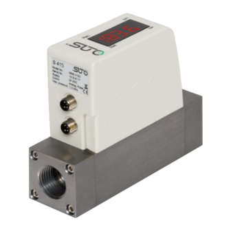
Compact thermal mass flow meter (eco-inline)
Hide thumbs
Also See for S415:
- Instruction and operation manual (24 pages) ,
- Instruction and operation manual (24 pages)

Related Manuals for SUTO S415


Summary of Contents for SUTO S415
- Page 1 English Instruction and Operation Manual S415 Compact Thermal Mass Flow Meter (Eco-Inline)
- Page 2 The device is destined exclusively for the described application. SUTO offers no guarantee for the suitability for any other purpose. SUTO is also not liable for consequential damage resulting from the delivery, capability or use of this device.
-
Page 3: Table Of Contents
9.3.2.2 Modbus/RTU Wiring and Cable Type......20 9.3.2.3 Create Daisy-Chain using RS-485 Splitter....21 9.3.2.4 Topology of Modbus/RTU Daisy-Chain......22 9.4 M-Bus Output..............23 9.5 Connection between S415 Outputs and Customer Equipment..23 10 Configuration................25 11 Calibration................26 12 Disposal or Waste..............26 13 Appendix A - Specifications............27 13.1 Flow Ranges..............27... -
Page 4: Safety Instructions
• Consider all regulations for electrical installations. • The system must be disconnected from any power supply during maintenance. • Any electrical work on system is only allowed by authorized qualified personal. S415... - Page 5 • Always observe the direction of the flow when installing the device. The direction is indicated on the housing. • Do not exceed the maximum operating temperature at the sensors tip. • Avoid condensation on the sensor element as this will affect accuracy enormously. S415...
-
Page 6: Registered Trademarks
• Avoid direct UV and solar radiation during storage. • For the storage the humidity must be <90% with no condensation. 2 Registered Trademarks Trademark Trademark owner SUTO SUTO iTEC ® MODBUS ® Modbus Organization, Hopkinton, USA Android™, Google LLC... -
Page 7: Rf Exposure Information And Statement
• Connect the equipment into an outlet on a circuit different from that to which the receiver is connected. • Consult the dealer or an experienced radio/TV technician for help • This device and its antenna(s) must not be co-located or operating in conjunction with any other antenna or transmitter. S415... -
Page 8: Application
4 Application 4 Application The S415 is the thermal mass flow meter that is designed to measure the volumetric flow and consumption of compressed air and nitrogen within the permitted operating parameters. (See Technical Data on the next page.) The default unit settings are: volumetric flow in l/min and total Consumption in m . -
Page 9: Technical Data
See dimensional drawing on page 11. Display 4-digit LED display Tube diameter DN8, DN15, DN20, DN25, and DN32 Process connection G inner thread ISO 228-1 Weight 0.45 kg (DN8), 0.44 kg (DN15) 0.97 kg (DN20), 0.94 kg (DN25) 1.7 kg (DN32) S415... -
Page 10: Electrical Data
27. Remark: The total consumption value is saved to the permanent memory every 5 minutes. If within these 5 minutes the device is powered off, it will restore the last consumption value which was saved in the last cycle. S415... -
Page 11: Dimensional Drawing
7 Dimensional Drawing 7 Dimensional Drawing Unit: mm DN8/DN15 S415... - Page 12 7 Dimensional Drawing DN20/DN25 S415...
- Page 13 7 Dimensional Drawing DN32 S415...
-
Page 14: Installation
• Due to the integrated flow conditioner, there are no additional straight pipe requirements for good measurement. However for best measurement, it is recommended 3-5 times inner diameter straight pipe at the inlet. • The S415 can be installed in horizontal or vertical pipes. S415... -
Page 15: Led Indicators
5 m cable with a M8 connector on one side and open wires on the other side. To make the S415 work, one cable connection is sufficient. However, if the pulse output is to be used or the supply and the signal need to be on separate cables, a second connection cable must be ordered. - Page 16 Pin 1 Pin 2 Pin 3 Pin 4 Modbus Pulse and analog M-Bus M-Bus M-Bus M-Bus M-Bus Wire color Brown White Blue Black ATTENTION! Do not screw the M8 plug using force. Otherwise, it may damage the connecting pins. S415...
-
Page 17: Signal Outputs
The flow meter outputs one pulse per a consumption unit. This pulse output can be connected to an external pulse counter to count the total consumption. The number of m per second are summed up and indicated after one second. Pulse length depends on flow rate. S415... -
Page 18: Modbus Interface
SEEEEEEE) (EMMMMMMM *) Byte 0 Byte 3 UINT32 1-0-3-2 Byte 1 Byte 2 INT32 Byte 1 Byte 0 UINT16 INT16 Byte 1 Byte 0 UINT8 XXX * DATA INT8 * S: Sign, E: Exponent, M: Mantissa, XXX: no value S415... -
Page 19: Connect Several S415 To Modbus Master
UNIT32 4-Byte 9.3.2 Connect Several S415 to Modbus Master The S415 with Modbus/RTU interface can be easily daisy-chained to a Modbus Master device. This master can be either SUTO displays and gateways or any third-party Modbus/RTU master. Through this method you can add up to 16 flow meters to the master device. -
Page 20: Modbus/Rtu Wiring And Cable Type
(A553 0123). • The shield must be connected at one end to the master GND connection. • At the end of the bus, a 120 Ohm resistor should be placed a termination resistor. See the below picture for details. S415... -
Page 21: Create Daisy-Chain Using Rs-485 Splitter
9 Signal Outputs 9.3.2.3 Create Daisy-Chain using RS-485 Splitter To connect the S415 to the daisy-chain, the RS-485 splitter (A554 3310) and the M8 to M12 converter cable (A553 0161) are needed. Furthermore place a M12 termination resistor (C219 0055) at the last splitter in the daisy-chain, as show in the figure below. -
Page 22: Topology Of Modbus/Rtu Daisy-Chain
9.3.2.1 Modbus/RTU Cable Length. Other connection topologies are not recommended and should be avoided. Avoid a connection of slaves to the master in ring or star topology. Avoid a star topology Avoid a ring topology S415... -
Page 23: M-Bus Output
M-Bus status 4-byte Connection between S415 Outputs and Customer Equipment This section provides figures to show how outputs supported by the S415 connect with the customer equipment. In the following figures, the SUTO Instrument indicates the S415. Analog output (Isolated) S415... - Page 24 9 Signal Outputs Pulse output (passive) Modbus/RTU output M-Bus output S415...
-
Page 25: Configuration
10 Configuration 10 Configuration To change any settings on the S415, download and install the mobile App S4C-FS from the Google Play store or the SUTO website. This App works on any mobile phone with Bluetooth supported. To be allowed to change settings, the App needs to scan the QR code attached on the side of the device head or on the calibration certificate. -
Page 26: Calibration
The device, the accessories and its packing must be disposed according to your local statutory requirements. The dispose can also be carried by the manufacturer of the product, for this please contact the manufacturer. S415... -
Page 27: Appendix A - Specifications
0°C and 1013.25 hPa Unit: l/min DN15 DN20 DN25 DN32 Min Max Min Standard 4.44 222 17.8 890 35.6 1780 62.2 3110 5335 range (S) 0.89 44.5 3.56 178 7.12 356 12.4 1067 range (L) S415... -
Page 28: Error Code
DN8 G inner thread DN15 G inner thread S695 415 DN20 G inner thread DN25 G inner thread DN32 G inner thread Standard range version of S415 A1453 Low range version of S415 A1450 Analogue 4 … 20 mA, pulse A1451... - Page 29 RS-485 splitter T, with 3 x M12 connectors to connect RS-485 A554 3310 devices to a bus. Mains power supply 100-240 VAC / 24 VDC, 0.5 A, 2 m cable A554 0109 with M8 connector A553 0137 Connection cable S415/S418 to S551, 5 m S415...
- Page 30 S415...
- Page 31 S415...
- Page 32 SUTO iTEC GmbH SUTO iTEC (ASIA) Co., Ltd. Grißheimer Weg 21 Room 10, 6/F, Block B, Cambridge Plaza D-79423 Heitersheim 188 San Wan Road, Sheung Shui, N.T. Germany Hong Kong Tel: +49 (0) 7634 50488 00 Tel: +852 2328 9782 Email: sales@suto-itec.com...
Need help?
Do you have a question about the S415 and is the answer not in the manual?
Questions and answers