
Related Manuals for SUTO S601


Summary of Contents for SUTO S601
- Page 1 English Instruction and Operation Manual S601 Stationary Compressed Air Purity Monitor...
- Page 2 The device is destined exclusively for the described application. SUTO offers no guarantee for the suitability for any other purpose. SUTO is also not liable for consequential damage resulting from the delivery, capability or use of this device.
-
Page 3: Table Of Contents
9.3 Graphic Screen................26 9.4 Menu..................26 9.4.1 Sensor Settings..............27 9.4.2 Alarm Setting...............28 9.4.3 Logger Setting..............29 9.4.4 Files..................30 9.4.5 Service Info ................30 9.4.6 System Setting..............31 9.4.7 Communication..............32 9.5 Configuring S601 using S4C-Display..........32 9.5.1 RS-485 Settings..............33 9.5.2 Ethernet Settings..............34 9.5.3 Modbus Interface..............35 S601... - Page 4 10 Software Installation...............37 11 Optional Accessories................37 12 Maintenance...................37 13 Disposal or Waste................38 14 Calibration..................38 15 Warranty..................39 S601...
-
Page 5: Safety Instructions
Any contact with energized parts of the product, may lead to an electrical shock which can lead to serious injuries or even death! • Consider all regulations for electrical installations. • The system must be disconnected from any power supply during maintenance work. S601... - Page 6 • It is not allowed to use the product in explosive areas. • Please observe the national regulations before/during installation and operation. Remarks • It is not allowed to disassemble the product. • Always check the compressed air connectors in terms of stability and tightness. S601...
- Page 7 • Observe the measuring point always before measurement if it is free of contamination like water drops, oil drops or other rough contamination. • Should water hit the inner electronics, the senors could be seriously damaged. • Check your measurement point with the enclosed test kit. S601...
-
Page 8: Registered Trademarks
1 Safety Instructions 2 Registered Trademarks SUTO ® Registered trademark of SUTO iTEC MODBUS ® Registered trademark of the Modbus Organization, Hopkinton, USA HART ® Registered trademark of the HART Communication Foundation, Austin, USA Android™, Trademark s of Android™, Google Play... -
Page 9: Application
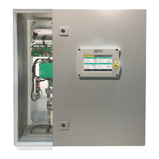
3 Application 3 Application The S601 Stationary Compressed Air Purity Monitor is a compact wall- mounted device that measures and records three major quality parameters of compressed air (particle quantity, dew point and temperature). The S601 is mainly used in industrial environments, and not developed to be used in explosive areas. -
Page 10: Technical Data
Dew point Polymer humidity sensor, oscillating crystal Oil vapor Resolution of oil 0.001 mg/m vapor sensor Medium Compressed air, non corrosive components Humidity of the < 40% rH, non condensation medium Temp. of the 0 ... +40°C medium S601... -
Page 11: Electrical Data
±1 °C Td (0 ... 20 °C Td) ±2 °C Td (-70 ... 0 °C Td) ±3 °C Td (-100 ... -70 °C Td) Oil vapor 5% of value ± 0.003 mg/m Temperature ± 0.2 K Pressure ± 0.08 bar S601... -
Page 12: Dimensions
6 Dimensions 6 Dimensions Dimensions in mm: S601... -
Page 13: Installation On Site
7 Installation on Site Please make sure that all components listed below are included in your package. Qty. Description Item No. S601 Stationary Compressed Air Purity D500 0601 Monitor in a wall mountable cabinet USB OTG memory stick A554 0087... -
Page 14: Mount The Unit At The Wall
7 Installation on Site 7.2 Mount the Unit at the Wall S601... -
Page 15: Electrical Connections
• A power supply connector (The cable is inserted through a PG plug and wires are connected to the internal screw terminals.) • An M12 RS-485 connector: To connect S601 to a RS-485 network • A RJ-45 Ethernet connector: To connect S601 to a TCP/IP network In addition, two alarm output relays are provided inside the S601 cabinet. -
Page 16: Rs-485 Networking (Modbus/Rtu)
Please observe voltage ranges and power levels! 7.3.2 RS-485 Networking (Modbus/RTU) Through the M12 connector at the bottom, the S601 can be connected to the RS-485 network over the Modbus/RTU protocol. The RS-485 network requires a termination resistor at both far ends of the RS-485 bus. -
Page 17: Tcp/Ip Networking (Modbus/Tcp)
Remove the protection cap and plug in the network cable (RJ-45). 7.3.4 Alarm Outputs S601 provides two relays for alarm outputs (230 VAC, 3 A) in the S601 cabinet. The following figure shows the back of the S601 display where the two alarm output relays (terminals H and I) are housed. -
Page 18: Compressed Air Connection
7 Installation on Site 7.4 Compressed Air Connection The S601 offers a compressed air inlet and an outlet at the bottom of the cabinet, next to the electrical connectors. S601 bottom view Installation precautions ATTENTION! Permissible pressure! Please observe the maximum permissible incoming pressure. -
Page 19: Connect Modbus/Rtu Sensors/Devices To A Master
3. Check the filter in the test kit for high contamination of water, oil or dust. 4. If the filter is contaminated severely, stop using the S601 to measure because this may lead to serious damage. In case you are not sure, please contact the manufacturer. -
Page 20: Modbus/Rtu Wiring And Cable Type
See the below picture for details. 7.5.3 Daisy-Chain using RS-485 Splitter SUTO devices with M12 connectors can be easily connected in a Modbus/RTU daisy-chain using a M12 RS-485 splitter (A554 3310). Furthermore this allows to easily place the M12 termination resistor (C219 0055) at the last splitter in the bus-chain. - Page 21 7 Installation on Site Connect Modbus/RTU slaves with M12 connectors to a daisy-chain using M12 RS-485 splitters. The M12 RS-485 splitter (A554 3310) comes with two M12 connectors to easily wire the chain. S601...
-
Page 22: Topology Of Modbus/Rtu Daisy-Chain
7.5.1 Modbus/RTU Cable Length. Other connection topologies are not recommended and must be avoided. Avoid a connection of slaves to the master in ring or star topology. Avoid a star topology Avoid a ring topology S601... -
Page 23: Setup
8 Setup 8 Setup The S601 is configured ex-work and ready to measure out of the box. The setup settings are saved in the device and will not be lost even after a power failure. To ensure an accurate measurement, before measurement, configure the altitude where the device is placed. -
Page 24: Main Screen
Type of the connected Sensor unit is not sensor does not match with matching with the sensor type configured configuration. in the device. RTC backup battery Logger status status Calibration is expired. Please contact the Alarm triggered manufacturer or your local dealer. S601... -
Page 25: Value Screen
Value in the bottom bar. Remark: During the first five minutes, the S601 automatically performs a purge process to ensure any remaining particles in the system are blown out. During this period, the counting numbers on the Particle pane appear green and blink. -
Page 26: Graphic Screen
Shows the dynamic graphs of all measurements. To view the graphic screen, press Graphic in the bottom bar. The graphic view is pre-configured in the factory. You can view the S601 measurement graph without configuring anything. In case that you want to manipulate the graph, follow the instructions indicated in the following figure. -
Page 27: Sensor Settings
To ensure an accurate oil vapor measurement, enter the altitude where the S601 is placed. The valid values can be positive only. If the S601 is placed at a negative altitude, please enter 0 instead of the actual negative value. S601... -
Page 28: Alarm Setting
9 Operations and Configurations 9.4.2 Alarm Setting Enables you to define alarms in the S601. The S601 offers two alarm relay outputs and an optical alarm indication (flashing value). Channel Select a channel to be configured. Unit The unit is shown automatically after the channel is selected. -
Page 29: Logger Setting
After setting the alarms, you can view the activated alarms or dismiss some alarms through Menu > Alarm > Activated alarm. ATTENTION! Before installing the relay module, turn off the S601. After the relay module is installed, power on the S601 again. Otherwise, the normal use of the relay module may be affected. -
Page 30: Files
You can select a log file to view log details or to delete the file. 9.4.5 Service Info Enables you to view the contacts of the service provider, which can be input using the S4C-Display software. For more information about how to use S4C-Display, see section Configuring S601 using S4C-Display 。 S601... -
Page 31: System Setting
9 Operations and Configurations 9.4.6 System Setting Enables you to configure the S601 general settings. Password To configure a password to protect the S601 from unauthorized operations. Back light To adjust the back light brightness and the dimming timeout. Calibrate To calibrate the touch accuracy. -
Page 32: Communication
Enter the IP address or domain name of the S4M server. 9.5 Configuring S601 using S4C-Display To change the S601 settings, in addition to the S601 display, you can use the configuration software S4C-Display. You can download S4C- Display for free from the SUTO web page at www.suto-itec.com. -
Page 33: Rs-485 Settings
• Choose SUTO Protocol if the peer device is using SUTO software. Protocol selection • Choose Modbus if the S601 is connected to a Modbus network. Each device on the RS-485 network needs to have a Address unique device address. Please ensure that address 0 is not used and that there are no duplicated addresses. -
Page 34: Ethernet Settings
Modbus if device is connected to a Modbus selection network. After you select this option, the network router will dynamically assign the S601 an IP address. This is Get IP config convenient but not recommended in industrial automatically networks. It is recommended to assign a static IP address to the S601. -
Page 35: Modbus Interface
(MMMMMMMM *) SEEEEEEE) (EMMMMMMM *) Byte 0 Byte 3 UINT32 1-0-3-2 Byte 1 Byte 2 INT32 Byte 1 Byte 0 UINT16 INT16 Byte 1 Byte 0 UINT8 XXX * DATA INT8 *S: Sign, E: Exponent, M: Mantissa, XXX: no value S601... - Page 36 Device status particle UINT32_L Oil vapor FLOAT_L mg/m³ 0.001 Pressure FLOAT_L 0.01 Oil vapor sensor Serial number sensor UINT32_L Device status oil vapor UINT32_L Serial number display UINT32_L Display unit Serial number sensor rack UINT32_L Device status display UINT32_L S601...
-
Page 37: Software Installation
• Display unit serial number is the same number as the serial number of the complete S601 unit. 10 Software Installation Following software is available for download from www.suto-itec.com: S4C-Display Free configuration software Free logger readout and data analysis software... -
Page 38: Disposal Or Waste
It might be necessary to reset the displays storage during calibration and service. After you exchange a new sensor unit, remember to input its serial number to the S601 through Menu > System Setting > Device info. S601... -
Page 39: Warranty
Please find the warranty as a separated warranty card included with the instrument delivery. The warranty does not cover any wear parts or consumables, therefore the UV lamp with limited lifetime as well as the internal filter are not covered by the warranty. S601... - Page 40 SUTO iTEC GmbH SUTO iTEC (ASIA) Co., Ltd. Grißheimer Weg 21 Room 10, 6/F, Block B, Cambridge Plaza D-79423 Heitersheim 188 San Wan Road, Sheung Shui, N.T. Germany Hong Kong Tel: +49 (0) 7634 50488 00 Tel: +852 2328 9782 Email: sales@suto-itec.com...
Need help?
Do you have a question about the S601 and is the answer not in the manual?
Questions and answers