
Related Manuals for AUMA SAN 07.1


Summary of Contents for AUMA SAN 07.1
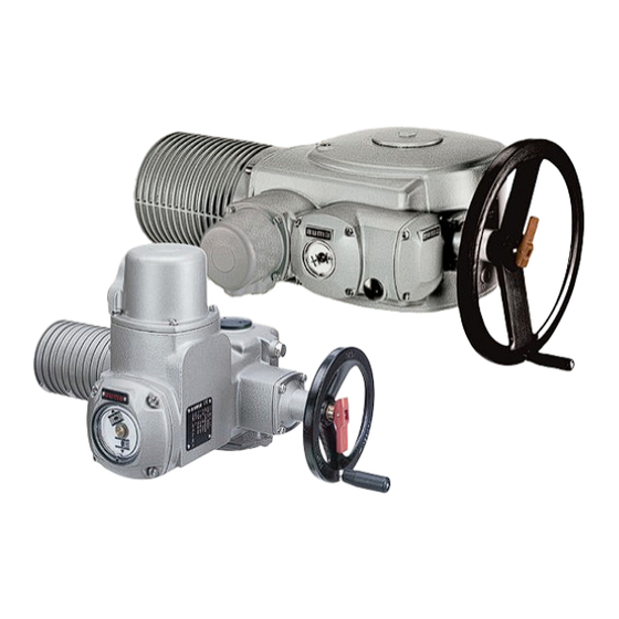
- Page 1 Electric multi-turn actuators for valve automation in nuclear power plants SAN 07.1 – SAN 25.1 SARN 07.1 – SARN 25.1 Operation instructions...
-
Page 2: Table Of Contents
These instructions are valid for multi-turn actuators of the type ranges Scope of these instructions: SAN 07.1 – SAN 25.1 and SARN 07.1 – SARN 25.1 for use outside the containment. These operation instructions are only valid for “clockwise closing”, i.e. - Page 3 Multi-turn actuators SAN 07.1 – SAN 25.1/SARN 07.1 – SARN 25.1 Operation instructions for valve automation in nuclear power plants Page Closing the switch compartment Enclosure protection IP 68 Maintenance Lubrication Disposal and recycling Service and training Spare parts list Multi-turn actuator SAN/SARN 07.1 - SAN/SARN 16.1 with plug/socket connector 26 Spare parts list Multi-turn actuator SAN/SARN 25.1...
-
Page 4: Safety Instructions
Multi-turn actuators SAN 07.1 – SAN 25.1/SARN 07.1 – SARN 25.1 for valve automation in nuclear power plants Operation instructions Safety instructions Range of application AUMA actuators are designed for the operation of industrial valves, e.g. globe valves, gate valves, butterfly valves, and ball valves. -
Page 5: Technical Data
Technical data Table 1: Multi-turn actuator SAN 07.1 – SAN 25.1/SARN 07.1 – SARN 25.1 General information AUMA actuators of type range SAN/SARN are qualified for use in Outside Containment, according to KTA 3504-1988 or IEEE 382 (1996). Features and functions... - Page 6 Multi-turn actuators SAN 07.1 – SAN 25.1/SARN 07.1 – SARN 25.1 for valve automation in nuclear power plants Operation instructions Lifetime SAN 07.1 – SAN 25.1: 5000 operations according to KTA 3504 SARN 07.1 – SARN 10.1: 2.5 million operations SARN 14.1 –...
-
Page 7: Transport, Storage And Packaging
Multi-turn actuators SAN 07.1 – SAN 25.1/SARN 07.1 – SARN 25.1 Operation instructions for valve automation in nuclear power plants Transport, storage and packaging Transport For transport to place of installation, use sturdy packaging. Do not attach ropes or hooks to the handwheel for the purpose of lifting by hoist. -
Page 8: Mounting To Valve/Gearbox
Multi-turn actuators SAN 07.1 – SAN 25.1/SARN 07.1 – SARN 25.1 for valve automation in nuclear power plants Operation instructions Mounting to valve/gearbox Prior to mounting the multi-turn actuator must be checked for damage. Damaged parts must be replaced by original spare parts. - Page 9 Multi-turn actuators SAN 07.1 – SAN 25.1/SARN 07.1 – SARN 25.1 Operation instructions for valve automation in nuclear power plants Finish machining of stem nut (output drive type A): Figure B-1 Output drive type A Stem nut 80.3 80.01/80.02 80.2 The output drive flange does not have to be removed from the actuator.
-
Page 10: Manual Operation
Multi-turn actuators SAN 07.1 – SAN 25.1/SARN 07.1 – SARN 25.1 for valve automation in nuclear power plants Operation instructions Manual operation The actuator may be operated manually for purposes of setting and commissioning, and in case of motor failure or power failure. -
Page 11: Electrical Connection
The terminal plan applicable to the actuator is attached to the handwheel 51.01 in a weather-proof bag, together with the operation instructions. In case the terminal plan is not available, it can be obtained from AUMA (state commission no., refer to name plate) or downloaded directly from the Internet (www.auma.com). -
Page 12: Motor Connection For The Sizes San/Sarn
Multi-turn actuators SAN 07.1 – SAN 25.1/SARN 07.1 – SARN 25.1 for valve automation in nuclear power plants Operation instructions Motor connection for the sizes SAN/SARN 25.1 For the size SA/SAR 25.1, the power for the motor is connected to separate terminals. -
Page 13: Limit And Torque Switches
Multi-turn actuators SAN 07.1 – SAN 25.1/SARN 07.1 – SARN 25.1 Operation instructions for valve automation in nuclear power plants Limit and torque switches Only the same potential can be switched on the two circuits (NC/NO Figure G-5 contact) of a limit or torque switch. If different potentials are to be switched simultaneously, tandem switches are required. -
Page 14: Opening The Switch Compartment
Multi-turn actuators SAN 07.1 – SAN 25.1/SARN 07.1 – SARN 25.1 for valve automation in nuclear power plants Operation instructions Opening the switch To be able to carry out the following settings (chapters 9. to 15.), the switch compartment compartment must be opened and, if installed, the indicator disc must be removed. -
Page 15: Setting The Limit Switching
Multi-turn actuators SAN 07.1 – SAN 25.1/SARN 07.1 – SARN 25.1 Operation instructions for valve automation in nuclear power plants Setting the limit switching Setting end position CLOSED (black section) Turn handwheel clockwise until valve is closed. After having reached the end position, turn back handwheel by approximately ½... -
Page 16: Setting Of The Duo Limit Switching (Option)
Multi-turn actuators SAN 07.1 – SAN 25.1/SARN 07.1 – SARN 25.1 for valve automation in nuclear power plants Operation instructions 10. Setting the DUO limit switching (option) Any application can be switched on or off via the two intermediate position switches. -
Page 17: Setting The Torque Switching
Multi-turn actuators SAN 07.1 – SAN 25.1/SARN 07.1 – SARN 25.1 Operation instructions for valve automation in nuclear power plants 11. Setting the torque switching 11.1 Setting The set torque must suit the valve! This setting must only be changed with the consent of the... -
Page 18: Test Run
Multi-turn actuators SAN 07.1 – SAN 25.1/SARN 07.1 – SARN 25.1 for valve automation in nuclear power plants Operation instructions 12. Test run 12.1 Check direction of rotation If provided, place indicator disc on shaft. The direction of rotation of the indicator disc (figure M-1) indicates the direction of rotation of the output drive. -
Page 19: Setting The Potentiometer (Option)
Multi-turn actuators SAN 07.1 – SAN 25.1/SARN 07.1 – SARN 25.1 Operation instructions for valve automation in nuclear power plants 13. Setting the potentiometer (option) – For remote indication – Move valve to end position CLOSED. If installed, pull off indicator disc. -
Page 20: Setting The Electronic Position Transmitter Rwg (Option)
Multi-turn actuators SAN 07.1 – SAN 25.1/SARN 07.1 – SARN 25.1 for valve automation in nuclear power plants Operation instructions 14. Setting the electronic position transmitter RWG (option) – For remote indication or external control –- The electronic position transmitter RWG can only be used under normal conditions. -
Page 21: Setting 2-Wire System 4 - 20 Ma And 3-/4-Wire System 0 - 20 Ma
Multi-turn actuators SAN 07.1 – SAN 25.1/SARN 07.1 – SARN 25.1 Operation instructions for valve automation in nuclear power plants 14.1 Setting 2-wire system 4 – 20 mA and 3- /4-wire system 0 – 20 mA Connect voltage to electronic position transmitter. -
Page 22: Setting 3-/4- Wire System 4 - 20 Ma
Multi-turn actuators SAN 07.1 – SAN 25.1/SARN 07.1 – SARN 25.1 for valve automation in nuclear power plants Operation instructions 14.2 Setting 3- /4- wire system 4 – 20 mA Connect voltage to electronic position transmitter. Move valve to end position CLOSED. -
Page 23: Setting The Mechanical Position Indicator (Option)
Multi-turn actuators SAN 07.1 – SAN 25.1/SARN 07.1 – SARN 25.1 Operation instructions for valve automation in nuclear power plants 15. Setting the mechanical position indicator (option) Place indicator disc on shaft. Move valve to end position CLOSED. Turn lower indicator disc (figure Q1) until symbol CLOSED is in alignment with the mark on the cover (figure Q-2). -
Page 24: Enclosure Protection Ip
After maintenance, check multi-turn actuator for damage to paint finish. If damage to paint-finish has occurred after mounting, it has to be touched up to avoid corrosion. Original paint in small quantities can be supplied by AUMA. AUMA multi-turn actuators require very little maintenance. -
Page 25: Lubrication
Multi-turn actuators SAN 07.1 – SAN 25.1/SARN 07.1 – SARN 25.1 Operation instructions for valve automation in nuclear power plants Seals made of elastomers are subject to ageing and must therefore regularly be checked and, if necessary, exchanged. It is also very important that the O-rings at the covers are placed correctly and cable glands fastened firmly to prevent ingress of dirt or water. -
Page 26: Spare Parts List Multi-Turn Actuator San/Sarn 07.1 - San/Sarn 16.1 With Plug/Socket Connector
Multi-turn actuators SAN 07.1 – SAN 25.1/SARN 07.1 – SARN 25.1 for valve automation in nuclear power plants Operation instructions 22. Spare parts list Multi-turn actuator SAN/SARN 07.1 – SAN/SARN 16.1 with plug/socket connector... - Page 27 Please state type and commission no. of the device (see name plate) when ordering spare parts. Only original AUMA spare parts should be used. Failure to use original spare parts voids the warranty and exempts AUMA from any liability. Delivered spare parts may slightly vary from the representation.
-
Page 28: Spare Parts List Multi-Turn Actuator San/Sarn
Multi-turn actuators SAN 07.1 – SAN 25.1/SARN 07.1 – SARN 25.1 for valve automation in nuclear power plants Operation instructions 23. Spare parts list Multi-turn actuator SAN/SARN 25.1... - Page 29 Note: Please state type and commission no. of the device (see name plate) when ordering spare parts. Only original AUMA spare parts should be used. Failure to use original spare parts voids the warranty and exempts AUMA from any liability.
-
Page 30: Declaration Of Incorporation And Ec Declaration Of Conformity
Multi-turn actuators SAN 07.1 – SAN 25.1/SARN 07.1 – SARN 25.1 for valve automation in nuclear power plants Operation instructions 24. Declaration of Incorporation and EC Declaration of Conformity... -
Page 31: Index
Multi-turn actuators SAN 07.1 – SAN 25.1/SARN 07.1 – SARN 25.1 Operation instructions for valve automation in nuclear power plants Index Ambient temperature Lifetime Safety instructions Limit switch Self locking Limit switching 15,16 Service Corrosion protection 7,24 Lubrication Service conditions... -
Page 32: Addresses Of Auma Offices And Representatives
AUMA Riester GmbH & Co. KG P.O. Box 1362 DE 79373 Muellheim Tel +49 7631 809 - 0 Fax +49 7631 809 - 1250 info@auma.com www.auma.com For detailed information about AUMA products, refer to the Internet: Y000.574/003/en/1.1 www.auma.com...
Need help?
Do you have a question about the SAN 07.1 and is the answer not in the manual?
Questions and answers