Table of Contents

Related Manuals for AUMA SAN 07.2


Summary of Contents for AUMA SAN 07.2
- Page 1 Multi-turn actuators SAN 07.2 SAN 16.2 SARN 07.2 SARN 14.6 AUMA NORM actuator (without controls) for use in nuclear power plants according to BSTS (UK-DITCTR-2020-EN-0257, Rev. D) Operation instructions Assembly, operation, commissioning...
-
Page 2: Table Of Contents
5.3.2. Output drive types B 5.3.2.1. Mount multi-turn actuator with output drive type B Electrical connection......................6.1. Basic information 6.2. S/SH electrical connection (AUMA plug/socket connector) 6.2.1. Open terminal compartment 6.2.2. Cable connection 6.2.3. Close terminal compartment 6.3. Accessories for electrical connection 6.3.1. - Page 3 SAN 07.2 SAN 16.2 / SARN 07.2 SARN 14.6 for use in nuclear power plants Table of contents 9.2. Feedback signals from actuator, for wiring diagrams TPA...-Y02 9.3. Feedback signals from actuator, for wiring diagrams TPA...-Y03 Commissioning (basic settings), for wiring diagrams TPA...-Y01........
- Page 4 Servicing and maintenance....................15.1. Preventive measures for servicing and safe operation 15.2. Maintenance 15.3. Disposal and recycling Technical data......................... 16.1. Technical data Multi-turn actuators Spare parts..........................17.1. Multi-turn actuators SAN 07.2 SAN 16.2/SARN 07.2 SARN 14.6 according to BSTS Index............................
-
Page 5: Safety Instructions
Any device modification requires prior written consent of the manufacturer. 1.2. Range of application AUMA multi-turn actuators are designed for the operation of industrial valves, e.g. globe valves, gate valves, butterfly valves, and ball valves. The actuators are qualified for use in nuclear power plants outside containment. -
Page 6: Warnings And Notes
SAN 07.2 SAN 16.2 / SARN 07.2 SARN 14.6 Safety instructions for use in nuclear power plants Industrial trucks according to EN ISO 3691 Lifting appliances according to EN 14502 Passenger lifts according to DIN 15306 and 15309 Service lifts according to EN 81-1/A1... -
Page 7: Short Description
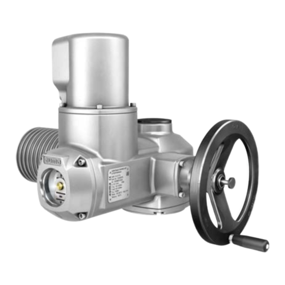
Valve attachment, e.g. output drive type A Mechanical position indicator AUMA SAN/SARN multi-turn actuators are driven by an electric motor. A handwheel is provided for occasional manual operation. Switching off in end positions may be either by limit or torque seating. In combination with output drive type A, the actuator is capable of withstanding thrust. -
Page 8: Name Plate
SAN 07.2 SAN 16.2 / SARN 07.2 SARN 14.6 Name plate for use in nuclear power plants Name plate Figure 2: Arrangement of name plates Motor name plate Actuator name plate Additional plate, e.g. KKS plate (Power Plant Classification System) - Page 9 11-digit, internal number for unambiguous product identification 2023 Year of manufacture = 2023 When registered as authorised user, you may use our AUMA Assistant App to scan Data Matrix code the Data Matrix code and directly access the order-related product documents without having to enter order number or serial number.
-
Page 10: Transport And Storage
Perform lift trial at low height to eliminate any potential danger e.g. by tilting. Figure 5: Example: Lifting the actuator Weights Table 4: Weights for multi-turn actuators SAN 07.2 SAN 16.2/SARN 07.2 SARN 16.2 with 3-phase AC motors Type designation... -
Page 11: Storage
VD... AD... Refer to motor name plate Indicated weight includes AUMA NORM multi-turn actuator with 3-phase AC motor, electrical con- nection in standard version, output drive type B1 and handwheel. For other output drive types, heed additional weights. Table 5:... -
Page 12: Assembly
Corrosion due to damage to paint finish! After all assembly work at the device, check housing for damage to paint. Carefully touch up damage to paint so that the initial delivery status is restored. Original paint in small quantities can be supplied by AUMA. -
Page 13: Output Drive Type A
SAN 07.2 SAN 16.2 / SARN 07.2 SARN 14.6 for use in nuclear power plants Assembly 5.3.1. Output drive type A Figure 7: Output drive type A Output mounting flange Stem nut Valve stem Output drive type A consisting of output mounting flange [1] with axial bearing stem Short description nut [2]. - Page 14 SAN 07.2 SAN 16.2 / SARN 07.2 SARN 14.6 Assembly for use in nuclear power plants Place output drive type A [2] on valve stem and turn until it is [4] flush on the valve flange. Turn output drive type A [2] until alignment of the fixing holes.
-
Page 15: 5.3.1.2. Finsh Machining Of Stem Nut For Output Drive Type A
5.3.1.2. Finsh machining of stem nut for output drive type A This working step is only required if stem nut is supplied unbored or with pilot bore. Information For exact product version, please refer to the order-related technical data sheet or the AUMA Assistant App. - Page 16 SAN 07.2 SAN 16.2 / SARN 07.2 SARN 14.6 Assembly for use in nuclear power plants Figure 12: Output drive type A Stem nut Axial needle roller bearing [2.1] Axial bearing washer [2.2] Axial needle roller and cage assembly Spigot ring O-ring Remove spigot ring [3] from output drive.
-
Page 17: Output Drive Types B
SAN 07.2 SAN 16.2 / SARN 07.2 SARN 14.6 for use in nuclear power plants Assembly 5.3.2. Output drive types B Figure 13: Mounting principle, example output drive type B Flange multi-turn actuator (e.g. F07) Hollow shaft Output drive sleeve (illustration examples) -
Page 18: 5.3.2.1. Mount Multi-Turn Actuator With Output Drive Type B
SAN 07.2 SAN 16.2 / SARN 07.2 SARN 14.6 Assembly for use in nuclear power plants 5.3.2.1. Mount multi-turn actuator with output drive type B Figure 14: Mounting output drive types B Multi-turn actuator Valve/gearbox Valve/gearbox shaft Check if mounting flanges fit together. -
Page 19: Electrical Connection
Wiring diagram/terminal the device in a weather-proof bag, together with these operation instructions. It can plan also be requested from AUMA (state order number, refer to name plate) or downloaded directly from the Internet (http://www.auma.com). Valve damage for connection without controls! NORM actuators require controls: Connect motor via actuator controls only (reversing contactor circuit). - Page 20 SAN 07.2 SAN 16.2 / SARN 07.2 SARN 14.6 Electrical connection for use in nuclear power plants Figure 15: Motor name plate (example) Type of current Mains voltage Mains frequency For short-circuit protection and for disconnecting the actuator from the mains, fuses Protection and sizing on and disconnect switches have to be provided by the customer.
-
Page 21: S/Sh Electrical Connection (Auma Plug/Socket Connector)
Control contacts also available as crimp-type connection as an option. S version (standard) with three cable entries. SH version (enlarged) with additional cable entries. For cable connection, remove the AUMA plug/socket connector and the socket carrier from cover. -
Page 22: Open Terminal Compartment
SAN 07.2 SAN 16.2 / SARN 07.2 SARN 14.6 Electrical connection for use in nuclear power plants 6.2.1. Open terminal compartment Figure 17: Open terminal compartment Cover (figure shows S version) Screws for cover O-ring Screws for socket carrier Socket carrier... -
Page 23: Cable Connection
SAN 07.2 SAN 16.2 / SARN 07.2 SARN 14.6 for use in nuclear power plants Electrical connection 6.2.2. Cable connection Table 10: Terminal cross sections and terminal tightening torques Designation Terminal cross sections Tightening torques Power contacts 6 mm (flexible) 1.5 Nm... -
Page 24: Close Terminal Compartment
SAN 07.2 SAN 16.2 / SARN 07.2 SARN 14.6 Electrical connection for use in nuclear power plants For shielded cables: Link the cable shield end via the cable gland to the housing (earthing). 6.2.3. Close terminal compartment Figure 20: Close terminal compartment... -
Page 25: Accessories For Electrical Connection
SAN 07.2 SAN 16.2 / SARN 07.2 SARN 14.6 for use in nuclear power plants Electrical connection 6.3. Accessories for electrical connection 6.3.1. External earth connection Figure 21: Earth connection for multi-turn actuator External earth connection (U-bracket) for connection to equipotential compensation. -
Page 26: Operation
SAN 07.2 SAN 16.2 / SARN 07.2 SARN 14.6 Operation for use in nuclear power plants Operation 7.1. Manual operation For purposes of setting and commissioning, in case of motor or power failure, the actuator may be operated manually. Manual operation is engaged by an internal change-over mechanism. -
Page 27: Indications (Option)
SAN 07.2 SAN 16.2 / SARN 07.2 SARN 14.6 for use in nuclear power plants Indications (option) Indications (option) 8.1. Mechanical position indication via indicator mark Figure 23: Mechanical position indicator End position OPEN reached End position CLOSED reached Indicator mark at cover... -
Page 28: Signals (Output Signals)
SAN 07.2 SAN 16.2 / SARN 07.2 SARN 14.6 Signals (output signals) for use in nuclear power plants Signals (output signals) 9.1. Feedback signals from actuator, for wiring diagrams TPA...-Y01 Switches can be provided as toggle switches (1 NC and 1 NO) or as tandem switches Information (2 NC and 2 NO). - Page 29 SAN 07.2 SAN 16.2 / SARN 07.2 SARN 14.6 for use in nuclear power plants Signals (output signals) 9.3. Feedback signals from actuator, for wiring diagrams TPA...-Y03 Switches can be provided as toggle switches (1 NC and 1 NO) or as tandem switches Information (2 NC and 2 NO).
-
Page 30: Commissioning (Basic Settings), For Wiring Diagrams Tpa
SAN 07.2 SAN 16.2 / SARN 07.2 SARN 14.6 Commissioning (basic settings), for wiring diagrams TPA...-Y01 for use in nuclear power plants Commissioning (basic settings), for wiring diagrams TPA...-Y01 10.1. Open switch compartment The switch compartment must be opened to perform the following settings. -
Page 31: Set Limit Switching
SAN 07.2 SAN 16.2 / SARN 07.2 SARN 14.6 for use in nuclear power plants Commissioning (basic settings), for wiring diagrams TPA...-Y01 Figure 24: Torque switching heads Torque switching head black in direction CLOSE Torque switching head white in direction OPEN... -
Page 32: Set End Position Open (White Section)
SAN 07.2 SAN 16.2 / SARN 07.2 SARN 14.6 Commissioning (basic settings), for wiring diagrams TPA...-Y01 for use in nuclear power plants Turn handwheel by approximately half a turn (overrun) in the opposite direction. Press down and turn setting spindle [1] with screw driver in direction of the arrow and observe the pointer [2]: While a ratchet click is felt and heard, the pointer [2] moves 90°... -
Page 33: Set Running Direction Close (Black Section)
SAN 07.2 SAN 16.2 / SARN 07.2 SARN 14.6 for use in nuclear power plants Commissioning (basic settings), for wiring diagrams TPA...-Y01 Information After 177 turns (control unit for 2 500 turns/stroke) or 1,769 turns (control unit for 5,000 turns/stroke), the intermediate switches release the contact. -
Page 34: Check Direction Of Rotation At Hollow Shaft/Stem
SAN 07.2 SAN 16.2 / SARN 07.2 SARN 14.6 Commissioning (basic settings), for wiring diagrams TPA...-Y01 for use in nuclear power plants Move actuator manually to intermediate position or to sufficient distance from end position. Switch on actuator in direction CLOSE and observe the direction of rotation on... -
Page 35: Close Switch Compartment
After all assembly work at the device, check housing for damage to paint. Carefully touch up damage to paint so that the initial delivery status is restored. Original paint in small quantities can be supplied by AUMA. Clean sealing faces of housing and cover. -
Page 36: Commissioning (Basic Settings), For Wiring Diagrams Tpa
SAN 07.2 SAN 16.2 / SARN 07.2 SARN 14.6 Commissioning (basic settings), for wiring diagrams TPA...-Y02 for use in nuclear power plants Commissioning (basic settings), for wiring diagrams TPA...-Y02 Opening via limit switches, closing via torque switches. Information 11.1. Open switch compartment The switch compartment must be opened to perform the following settings. -
Page 37: Set Torque Switching
SAN 07.2 SAN 16.2 / SARN 07.2 SARN 14.6 for use in nuclear power plants Commissioning (basic settings), for wiring diagrams TPA...-Y02 During actuator operation in direction CLOSE, it can be checked by operating the torque switch [1] in downward direction (direction TSC) whether the actuator switches off. -
Page 38: Open Motor Tripping/Limit Switching Bypass
SAN 07.2 SAN 16.2 / SARN 07.2 SARN 14.6 Commissioning (basic settings), for wiring diagrams TPA...-Y02 for use in nuclear power plants 11.4. Open motor tripping/limit switching bypass Figure 32: Setting elements for limit switching Black section: Setting spindle: End position CLOSED... -
Page 39: Set Motor Tripping Open (White Section)
SAN 07.2 SAN 16.2 / SARN 07.2 SARN 14.6 for use in nuclear power plants Commissioning (basic settings), for wiring diagrams TPA...-Y02 Press down and turn setting spindle [5] with screwdriver in direction of the arrow and observe the pointer [4]: While a ratchet click is felt and heard, the pointer [4] moves 90°... -
Page 40: Signalling The End Position Via Intermediate Position Switches
SAN 07.2 SAN 16.2 / SARN 07.2 SARN 14.6 Commissioning (basic settings), for wiring diagrams TPA...-Y02 for use in nuclear power plants 11.5. Signalling the end position via intermediate position switches Actuators equipped with DUO limit switching are equipped with two intermediate position switches. -
Page 41: Test Run
SAN 07.2 SAN 16.2 / SARN 07.2 SARN 14.6 for use in nuclear power plants Commissioning (basic settings), for wiring diagrams TPA...-Y02 Press down and turn setting spindle [4] with screwdriver in direction of the arrow and observe the pointer [5]: While a ratchet click is felt and heard, the pointer [5] moves 90°... -
Page 42: Check Direction Of Rotation At Hollow Shaft/Stem
After all assembly work at the device, check housing for damage to paint. Carefully touch up damage to paint so that the initial delivery status is restored. Original paint in small quantities can be supplied by AUMA. Clean sealing faces of housing and cover. - Page 43 SAN 07.2 SAN 16.2 / SARN 07.2 SARN 14.6 for use in nuclear power plants Commissioning (basic settings), for wiring diagrams TPA...-Y02 Apply a thin film of non-acidic grease (e.g. petroleum jelly) to the O-ring and insert it correctly. Figure 36: Place cover [1] on switch compartment.
-
Page 44: Commissioning (Basic Settings), For Wiring Diagrams Tpa
SAN 07.2 SAN 16.2 / SARN 07.2 SARN 14.6 Commissioning (basic settings), for wiring diagrams TPA...-Y03 for use in nuclear power plants Commissioning (basic settings), for wiring diagrams TPA...-Y03 Opening and closing via torque switches. Information 12.1. Open switch compartment The switch compartment must be opened to perform the following settings. -
Page 45: Set Torque Switching
SAN 07.2 SAN 16.2 / SARN 07.2 SARN 14.6 for use in nuclear power plants Commissioning (basic settings), for wiring diagrams TPA...-Y03 During actuator operation in direction CLOSE, it can be checked by operating the torque switch [1] in downward direction (direction TSC) whether the actuator switches off. -
Page 46: Open Motor Tripping/Torque Switching Bypass
SAN 07.2 SAN 16.2 / SARN 07.2 SARN 14.6 Commissioning (basic settings), for wiring diagrams TPA...-Y03 for use in nuclear power plants 12.4. Open motor tripping/torque switching bypass Figure 39: Setting elements for torque switching Black section: Setting spindle: End position CLOSED... -
Page 47: Set The By-Pass Of The Torque Switch Close (White Section)
SAN 07.2 SAN 16.2 / SARN 07.2 SARN 14.6 for use in nuclear power plants Commissioning (basic settings), for wiring diagrams TPA...-Y03 Press down and turn setting spindle [5] with screwdriver in direction of the arrow and observe the pointer [4]: While a ratchet click is felt and heard, the pointer [4] moves 90°... -
Page 48: Signalling The End Position Via Intermediate Position Switches
SAN 07.2 SAN 16.2 / SARN 07.2 SARN 14.6 Commissioning (basic settings), for wiring diagrams TPA...-Y03 for use in nuclear power plants 12.5. Signalling the end position via intermediate position switches Actuators equipped with DUO limit switching are equipped with two intermediate position switches. -
Page 49: Test Run
SAN 07.2 SAN 16.2 / SARN 07.2 SARN 14.6 for use in nuclear power plants Commissioning (basic settings), for wiring diagrams TPA...-Y03 Press down and turn setting spindle [4] with screwdriver in direction of the arrow and observe the pointer [5]: While a ratchet click is felt and heard, the pointer [5] moves 90°... -
Page 50: Check Direction Of Rotation At Hollow Shaft/Stem
After all assembly work at the device, check housing for damage to paint. Carefully touch up damage to paint so that the initial delivery status is restored. Original paint in small quantities can be supplied by AUMA. Clean sealing faces of housing and cover. - Page 51 SAN 07.2 SAN 16.2 / SARN 07.2 SARN 14.6 for use in nuclear power plants Commissioning (basic settings), for wiring diagrams TPA...-Y03 Apply a thin film of non-acidic grease (e.g. petroleum jelly) to the O-ring and insert it correctly. Figure 43: Place cover [1] on switch compartment.
-
Page 52: Commissioning (Optional Equipment Settings)
SAN 07.2 SAN 16.2 / SARN 07.2 SARN 14.6 Commissioning (optional equipment settings) for use in nuclear power plants Commissioning (optional equipment settings) 13.1. Potentiometer The potentiometer is used as travel sensor and records the valve position. The potentiometer is housed in the actuator switch compartment. The switch Setting elements compartment must be opened to perform any settings. - Page 53 SAN 07.2 SAN 16.2 / SARN 07.2 SARN 14.6 for use in nuclear power plants Commissioning (optional equipment settings) Hold lower indicator disc in position and turn upper disc with symbol (OPEN) until it is in alignment with the mark on the cover.
-
Page 54: Corrective Action
SAN 07.2 SAN 16.2 / SARN 07.2 SARN 14.6 Corrective action for use in nuclear power plants Corrective action 14.1. Faults during commissioning Table 18: Faults during operation/commissioning Fault Description/cause Remedy Mechanical position indicator cannot Reduction gearing is not suitable for turns/stroke Exchange reduction gearing. -
Page 55: Servicing And Maintenance
Therefore, we recommend contacting our service. Only perform servicing and maintenance tasks when the device is switched off. AUMA AUMA offers extensive service such as servicing and maintenance as well as Service & Support customer product training. For the contact addresses, refer to our website (www.auma.com). - Page 56 SAN 07.2 SAN 16.2 / SARN 07.2 SARN 14.6 Servicing and maintenance for use in nuclear power plants Arrange for controlled waste disposal of the disassembled material or for sep- arate recycling according to materials. Observe the national regulations for waste disposal.
-
Page 57: Technical Data
Information on the customer-specific version, refer to the order-related data sheet. The technical data sheet can be downloaded from the Internet in both German and English at ht- tp://www.auma.com (please state the order number). 16.1. Technical data Multi-turn actuators Features and functions... - Page 58 Dimensions SAN 07.2 SAN 16.2/SARN 07.2 SARN 16.2 Electrical data SAN 07.2 SAN 16.2 with 3-phase AC motor according to BSTS (UK-DITCTR-2020-EN- 0257, Rev. D) Qualification report QSR Y009.287/003 Electrical data SARN 07.2 SARN 14.6 with 3-phase AC motors according to BSTS (UK-DITCTR-2020- EN-0257, Rev.
-
Page 59: Spare Parts
SAN 07.2 SAN 16.2 / SARN 07.2 SARN 14.6 for use in nuclear power plants Spare parts Spare parts 17.1. Multi-turn actuators SAN 07.2 SAN 16.2/SARN 07.2 SARN 14.6 according to BSTS... - Page 60 Please state device type and our order number (see name plate) when ordering spare parts. Only original AUMA spare parts should be used. Failure to use original spare parts voids the warranty and exempts AUMA from any liability. Representation of spare parts may slightly vary from actual delivery.
-
Page 61: Index
SAN 07.2 SAN 16.2 / SARN 07.2 SARN 14.6 for use in nuclear power plants Index Index Limit switches Limit switching LOCA/DBE resistance Accessories (electrical con- LOCA/DBE temperature nection) Lubricant type Ambient temperature 8, 58 Lubrication Applications Assembly Assistant App... - Page 62 SAN 07.2 SAN 16.2 / SARN 07.2 SARN 14.6 Index for use in nuclear power plants Safety instructions Safety instructions/warnings Safety measures Safety standards Screw plugs Self-locking Serial number 8, 9 Service Servicing Short-circuit protection Signals Spare parts Speed Standards...
- Page 64 AUMA Riester GmbH & Co. KG P.O. Box 1362 DE 79373 Muellheim Tel +49 7631 809 - 0 Fax +49 7631 809 - 1250 info@auma.com www.auma.com Y009.335/003/en/1.23 For detailed information on AUMA products, refer to the Internet: www.auma.com...
Need help?
Do you have a question about the SAN 07.2 and is the answer not in the manual?
Questions and answers