Table of Contents
Advertisement
Quick Links
EN50155
Switch
Q
I
I N D U S T R I A L
uick
nstallation
Introduction
T M
ORing's Transporter
series managed PoE Ethernet switches are designed
for industrial applications, such as rolling stock, vehicle, and railway
applications.
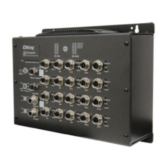
TGPS-9164GT-M12X-BP2-MV
E t h e r n e t s w i t c h w i t h 1 6 x 1 0 / 1 0 0 / 1 0 0 0 B a s e - T ( X ) P. S . E . a n d
4x10/100/1000Base-T(X) ports which is specifically designed for the
toughest and fully compliant with EN50155 requirement. The switch support
Ethernet Redundancy protocol, O-Ring (recovery time < 30ms over 250
units of connection), O-Chain, MRP
*NOTE
802.1s/w/D) can protect your mission-critical applications from network
interruptions or temporary malfunctions with its fast recovery technology.
TGPS-9164GT-M12X-BP2-MV also support Power over Ethernet, a system
to transmit electrical power up to 30 watts, along with data, to remote
devices over standard twisted-pair cable in an Ethernet network.
TGPS-9164GT-M12X-BP2-MV switch has 16x10/100/1000Base-T(X)
P.S.E. (Power Sourcing Equipment) ports. P.S.E. is a device (switch or hub
for instance) that will provide power in a PoE connection. TGPS-9164GT-
M12X-BP2-MV includes 2 sets of bypass ports that protect the network from
failures and Network maintenance by ensuring network integrity during
power loss. And support wide operating temperature from -40 C to 75 C.
TGPS-9164GT-M12X-BP2-MV can also be managed centralized and
convenient by Open-Vision, Except the Web-based interface, Telnet and
console (CLI) configuration.
Therefore, the switch is one of the most
reliable choices for EN50155 highly-managed Ethernet application.
*Note: This function is available by request only.
Package Contents
The device is shipped with the following items. If any of these items is
missing or damaged, please contact your customer service representative
for assistance.
Contents
Pictures
TGPS-9164GT-M12X-BP2-MV
CD
QIG
Preparation
Before you begin installing the device, make sure you have all of the
package contents available and a PC with Microsoft Internet Explorer 6.0 or
later, for using web-based system management tools.
Safety & Warnings
Elevated Operating Ambient: If installed in a closed environment, make sure
the operating ambient temperature is compatible with the maximum
ambient temperature (Tma) specified by the manufacturer.
Reduced Air Flow: Make sure the amount of air flow required for safe
operation of the equipment is not compromised during installation.
Mechanical Loading: Make sure the mounting of the equipment is not in a
hazardous condition due to uneven mechanical loading.
Q I G
TGPS-9164GT-M12X-BP2-MV
TGPS-9164GT-M12X-BP2-MV
G
uide
Circuit Overloading: Consideration should be given to the connection of the equipment to
the supply circuit and the effect that overloading of the circuits might have on overcurrent
protection and supply wiring. Appropriate consideration of equipment nameplate ratings
is managed Redundant Ring
should be used when addressing this concern.
Dimension
Unit =mm (Tolerance ±0.5mm)
and MSTP/RSTP/STP (IEEE
Each
o
o
89.6
Panel Layouts
Number
1
2
3 4 5
15
1
14
6
1
1
Installation
Wall-mount
The device can be fixed to the wall. Follow the steps below to install the device on the wall.
Step 1: Hold the
d
Step 2: Insert four screws through the large opening of the keyhole-shaped apertures at the
top and bottom of the unit and fasten the screws to the wall with a screwdriver.
Step 3: Slide the
d
1907-200-K9164X2MV1-FX010
Ø4.0
Ø5.0
Ø8.0
G5~G20
LNK/ACT
LNK/ACT
PoE
PoE
Speed
Speed
G16
G20
LNK/ACT
LNK/ACT
PoE
PoE
Speed
Speed
G15
G19
LNK/ACT
LNK/ACT
PoE
PoE
Speed
Speed
G14
G18
LNK/ACT
LNK/ACT
PoE
PoE
Speed
Speed
G13
G17
14.0
Front View
1. Reset button
2. Power status LED
3. R.M. status LED
4. Ring status LED
9
5. Fault LED
G5~G20
11
6. Power connector
LNK/ACT
LNK/ACT
12
PoE
PoE
13
7. Non-PoE Gigabit Ethernet ports with bypass
Speed
Speed
G16
G20
8. PoE-enabled Gigabit Ethernet ports
LNK/ACT
LNK/ACT
PoE
PoE
9. Link/ACT LED for non-PoE Gigabit ports
Speed
Speed
G15
G19
10. Speed LED for non-PoE Gigabit ports
LNK/ACT
LNK/ACT
11. Link/ACT LED for PoE-enabled Gigabit
PoE
PoE
Speed
Speed
ports
G14
G18
12. PoE indicator for PoE-enabled Gigabit
LNK/ACT
LNK/ACT
PoE
PoE
ports
Speed
Speed
G13
G17
13. Speed LED for PoE-enabled Gigabit ports
14. Console port
15. Relay output port
7
10
8
evice upright against the wall
evice downwards and tighten the four screws for added stability.
PRINTED ON RECYCLED PAPER
EN50155 20-port managed
Gigabit PoE Ethernet switch
Instead of screwing the screws in all the way, it is advised
to leave a space of about 2mm to allow room for sliding the
switch between the wall and the screws.
Wiring
For pin assignments of power, console and relay output ports, please refer to the following tables.
Grounding
Grounding and wire routing help limit the effects of noise due to electromagnetic interference
(EMI). Run the ground connection from the grounding pin on the power connector to the grounding
surface prior to connecting devices.
Power port pinouts
The device supports one set of power supply and uses the M12 S-coded
4-pin male connector on the front panel for power input.
Step 1: Insert a power cable to the power connector on the device.
Step 2: Rotate the outer ring of the cable connector until a snug fit is
achieved. Make sure the connection is tight.
Console port pinouts
RXD
TXD
N.C.
RSVD
GND
RS-232, 115200bps, 8, N, 1
Relay output port pinouts
The switch uses the M12 A-coded 5-pin female connector
on the front panel for relay output. Use a cable with an M12
A-coded 5-pin male connector to connect the relay. The
relay contacts will detect user-configured events and form
an close circuit when an event is triggered.
Network Connection
The switch has sixteen 10/100/1000Base-T(X) PoE and four 10/100/1000Base-T(X) non-PoE
Ethernet ports in the form of M12 connector. Depending on the link type, the switch uses CAT 3, 4,
5,5e UTP cables to connect to network devices (PCs, servers, switches, routers, or hubs). Please
refer to the following table for cable specifications.
Cable
Type
Max. Length
Connector
8-pin female M12
10BASE-T
Cat. 3, 4, 5 100-ohm
UTP 100 m (328 ft)
X-coding connector
8-pin female M12
100BASE-TX
Cat. 5 100-ohm UTP
UTP 100 m (328 ft)
X-coding connector
8-pin female M12
1000BASE-T
Cat. 5/Cat. 5e 100-ohm UTP UTP 100 m (328 ft)
X-coding connector
Quick Installation Guide
Version 1.0
N.C.
V+
V-
Relay
N.C.
3A@24VDC
Advertisement
Table of Contents

Subscribe to Our Youtube Channel
Related Manuals for ORiNG TGPS-9164GT-M12X-BP2-MV


Summary of Contents for ORiNG TGPS-9164GT-M12X-BP2-MV
- Page 1 MSTP/RSTP/STP (IEEE 802.1s/w/D) can protect your mission-critical applications from network interruptions or temporary malfunctions with its fast recovery technology. TGPS-9164GT-M12X-BP2-MV also support Power over Ethernet, a system to transmit electrical power up to 30 watts, along with data, to remote Wiring devices over standard twisted-pair cable in an Ethernet network.
- Page 2 For information on operating the RS-232 Serial Console Port RS-232 in M12 (female A-coding) connector with console cable. 115200bps, 8, N, 1 device using ORing’s Open-Vision management utility, please go to ORing website. Q I G Q I G...
Need help?
Do you have a question about the TGPS-9164GT-M12X-BP2-MV and is the answer not in the manual?
Questions and answers