ORiNG IGS-P9164 Series User Manual
Industrial iec 61850-3 managed gigabit ethernet switch
Hide thumbs
Also See for IGS-P9164 Series:
- Quick installation manual (2 pages) ,
- Quick installation manual (2 pages)
Table of Contents
Advertisement
Quick Links
I
G
S
-
P
I
G
S
-
P
I
n
d
u
s
t
r
i
a
l
I
E
I
n
d
u
s
t
r
i
a
l
I
E
G
i
g
a
b
i
t
E
G
i
g
a
b
i
t
U
s
e
U
s
e
V
V
9
1
6
4
S
e
r
i
e
9
1
6
4
S
e
r
i
e
C
6
1
8
5
0
-
3
M
C
6
1
8
5
0
-
3
M
t
h
e
r
n
e
t
S
w
E
t
h
e
r
n
e
t
S
w
r
M
a
n
u
a
l
r
M
a
n
u
a
l
e
r
s
i
o
n
1
.
0
e
r
s
i
o
n
1
.
0
J
u
l
y
,
2
0
1
5
J
u
l
y
,
2
0
1
5
s
s
a
n
a
g
e
d
a
n
a
g
e
d
i
t
c
h
i
t
c
h
w
w
w
.
o
r
i
n
g
-
n
e
t
w
o
w
w
w
.
o
r
i
n
g
-
n
e
t
w
r
k
i
n
g
.
c
o
m
o
r
k
i
n
g
.
c
o
m
Advertisement
Table of Contents

Subscribe to Our Youtube Channel
Related Manuals for ORiNG IGS-P9164 Series


Summary of Contents for ORiNG IGS-P9164 Series
-
Page 2: Copyright Notice
ORing warrants that all ORing products are free from defects in material and workmanship for a specified warranty period from the invoice date (5 years for most products). ORing will repair or replace products found by ORing to be defective within this warranty period, with shipment expenses apportioned by ORing and the distributor. -
Page 3: Table Of Contents
IGS-P9164 Series User Manual Table of Content Getting Started ....................6 About the IGS-P9164 Series ..................6 Software Features ....................6 Hardware Specifications ................... 7 Hardware Overview ..................8 Front Panel ....................... 8 2.1.1 Available Models ..................8 2.1.2 Ports and Connectors.................. 8 2.1.3... - Page 4 IGS-P9164 Series User Manual STP/RSTP/MSTP ....................26 4.5.1 STP/RSTP ....................26 4.5.2 MSTP ......................30 Fast Recovery ......................35 Management ....................36 Basic Settings ......................37 5.1.1 System Information ................... 37 5.1.2 Admin & Password ..................... 38 5.1.3 Authentication ..................... 39 5.1.4...
- Page 5 IGS-P9164 Series User Manual 5.5.3 SNMP User Configurations ............... 74 5.5.4 SNMP Group Configurations ..............76 5.5.5 SNMP View Configurations ............... 77 5.5.6 SNMP Access Configurations ..............78 Traffic Prioritization ....................79 5.6.1 Storm Control ...................... 79 5.6.2 Port Classification ....................79 5.6.3...
- Page 6 IGS-P9164 Series User Manual 5.10.3 Port Mirroring ................... 141 5.10.4 System Log Information ................142 5.10.5 Cable Diagnostics ................... 143 5.10.6 SFP Monitor .................... 143 5.10.7 Ping ......................144 5.10.8 IPv6 Ping ....................145 5.11 Synchronization ....................145 5.11.1 PTP External Clock Mode ............... 145 5.11.2...
-
Page 7: Getting Started
Started 1.1 About the IGS-P9164 Series The IGS-P9164 series is a managed industrial Ethernet switch designed for power substation and rolling stock applications as it is fully compliant with the requirements of IEC 61850-3 and IEEE 1613. The series consists of three models: IGS-P9164GF, IGS-P9164FX, and IGS-P9164GC, each comes with 16x10/100/1000Base-T(X) ports and differ numbers of optical fiber ports. -
Page 8: Hardware Specifications
IGS-P9164 Series User Manual Supports ACL, TACACS+ and 802.1x user authentication for secure connections Supports 9.6K Bytes Jumbo Frame Supports DBU-01 backup unit for fast backup/restore configuration Multiple notifications for warning of unexpected events Configuration via Web, Telnet, Console (CLI), and Windows utility (Open-Vision) ... -
Page 9: Hardware Overview
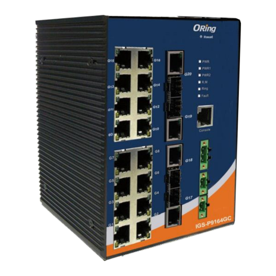
IGS-P9164 Series User Manual ardware Overview 2.1 Front Panel 2.1.1 Available Models Model name Description 16x10/100/1000Base-T(X) ports & 4x1000Base-X fiber ports with SC connector IGS-P9164GF 16x10/100/1000Base-T(X) ports & 4x100Base-FX fiber ports with SC connector IGS-P9164FX 16x10/100/1000Base-T(X) ports and 4xGigabit combo ports with SFP socket IGS-P9164GC 2.1.2 Ports and Connectors... - Page 10 IGS-P9164 Series User Manual IGS-P9164FX-HV IGS-P9164FX-LV IGS-P9164GC-HV IGS-P9164GC-LV ORing Industrial Networking Corp...
-
Page 11: Led
IGS-P9164 Series User Manual 1. LNK/ACT port for Ethernet ports 8. Power 2 module indicator 2. 10/100/100Base T(X) Ethernet ports 9. LED for Ring Master status 3. Fiber ports (IGS-P9164GF/GFX) or 10. LED for Ring status Combo ports (IGS-P9164GC) 11. Fault indicator 4. - Page 12 IGS-P9164 Series User Manual triangular patterns on both ends of the rear panel are used for wall-mounting (red boxes in the figure below) and the set of four holes in the middle are used for Din-rail installation (blue box in the figure below). For more information on installation, please refer to 23.1 Din-rail Installation.
-
Page 13: Hardware Installation
IGS-P9164 Series User Manual ardware Installation 3.1 DIN-rail Installation The device comes with a DIN-rail kit to allow you to fasten the switch to a DIN-rail in any environments. DIN-rail Kit Measurement (Unit = mm) Installing the switch on the DIN-rail is easy. First, screw the Din-rail kit onto the back of the switch, right in the middle of the back panel. - Page 14 IGS-P9164 Series User Manual Wall-Mount Kit Measurement (Unit = mm) To mount the switch onto the wall, follow the steps: 1. Screw the two pieces of wall-mount kits onto both ends of the rear panel of the switch. A total of six screws are required, as shown below.
-
Page 15: Wiring
IGS-P9164 Series User Manual Note: Instead of screwing the screws in all the way, leave about 2 mm to allow room for sliding the wall mount panel between the wall and the screws. 3.3 Wiring WARNING Do not disconnect modules or wires unless power has been switched off or the area is known to be non-hazardous. -
Page 16: Grounding
IGS-P9164 Series User Manual ATTENTION 1. Be sure to disconnect the power cord before installing and/or wiring your switches. 2. Calculate the maximum possible current in each power wire and common wire. Observe all electrical codes dictating the maximum current allowable for each wire size. -
Page 17: Connection
IGS-P9164 Series User Manual 3.4 Connection 3.4.1 Cables 10/100/1000BASE-T(X) Pin Assignments The series has standard Ethernet ports. According to the link type, the switch uses CAT 3, 4, 5,5e UTP cables to connect to any other network devices (PCs, servers, switches, routers, or hubs). - Page 18 IGS-P9164 Series User Manual BI_DB- BI_DD+ BI_DD- The series supports auto MDI/MDI-X operation. You can use a cable to connect the switch to a PC. The table below shows the 10/100Base-T(X) MDI and MDI-X port pin outs. 10/100Base-T(X) MDI/MDI-X Pin Assignments:...
-
Page 19: O-Ring/O-Chain
IGS-P9164 Series User Manual PC pin out (male) assignment RS-232 with DB9 female connector DB9 to RJ 45 Pin #2 RD Pin #2 TD Pin #2 Pin #3 TD Pin #3 RD Pin #3 Pin #5 GD Pin #5 GD Pin #5 3.4.2... - Page 20 IGS-P9164 Series User Manual Coupling Ring If you already have two O-Ring topologies and would like to connect the rings, you can form them into a couping ring. All you need to do is select two switches from each ring to be connected, for example, switch A and B from Ring 1 and switch C and D from ring 2.
- Page 21 IGS-P9164 Series User Manual O-Chain When connecting multiple O-Rings to meet your expansion demand, you can create an O-Chain topology through the following steps. 1. Select two switches from the chain (Switch A & B) that you want to connect to the O-Ring and connect them to the switches in the ring (Switch C &...
-
Page 22: Redundancy
4.1 O-Ring 4.1.1 Introduction O-Ring is ORing's proprietary redundant ring technology, with recovery time of less than 30 milliseconds (in full-duplex Gigabit operation) or 10 milliseconds (in full-duplex Fast Ethernet operation) and up to 250 nodes. The ring protocols identify one switch as the master of the network, and then automatically block packets from traveling through any of the network’s... - Page 23 IGS-P9164 Series User Manual Label Description Check to enable O-Ring topology. Enable Ring Only one ring master is allowed in a ring. However, if more than one switches are set to enable Ring Master, the switch with the Enable Ring Master lowest MAC address will be the active ring master and the others will be backup masters.
-
Page 24: Open-Ring
4.2 Open-Ring 4.2.1 Introduction Open-Ring is a technology developed by ORing to enhance ORing switches’ interoperability with other vendors’ products. With this technology, you can add any ORing switches to the network based on other ring technologies. 4.2.2 Configurations Label... -
Page 25: O-Chain
IGS-P9164 Series User Manual 4.3 O-Chain 4.3.1 Introduction O-Chain is ORing’s revolutionary network redundancy technology which enhances network redundancy for any backbone networks, providing ease-of-use and maximum fault-recovery swiftness, flexibility, compatibility, and cost-effectiveness in a set of network redundancy topologies. The self-healing Ethernet technology designed for distributed and complex... -
Page 26: Mrp
IGS-P9164 Series User Manual Label Description Enable Check to enable O-Chain function Ring Port The first port connecting to the ring Ring Port The second port connecting to the ring Edge Port An O-Chain topology must begin with edge ports. The ports with a smaller switch MAC address will serve as the backup link and RM LED will light up. -
Page 27: Stp/Rstp/Mstp
IGS-P9164 Series User Manual Label Description Enable Enables the MRP function Every MRP topology needs a MRP manager. One MRP Manager topology can only have a Manager. If two or more switches are set to be Manager, the MRP topology will fail. - Page 28 IGS-P9164 Series User Manual RSTP Bridge Setting Label Description Protocol Version Select Spanning Tree type , support STP / RSTP / MSTP A value used to identify the root bridge. The bridge with the lowest Bridge Priority (0-61440) value has the highest priority and is selected as the root. If the value changes, you must reboot the switch.
- Page 29 IGS-P9164 Series User Manual information to. Valid values are in the range 6 to 40 hops. Transmit Hold Count The number of BPDU's a bridge port can send per second. When exceeded, transmission of the next BPDU will be delayed. Valid values are in the range 1 to 10 BPDU's per second.
- Page 30 IGS-P9164 Series User Manual Label Description Port Port number STP Enable User can by port enable / disable STP Function Path Cost Auto User can setting Path Cost Auto or Specific Controls the path cost incurred by the port. The Auto setting...
-
Page 31: Mstp
IGS-P9164 Series User Manual administrator to prevent bridges external to a core region of the network influence the spanning tree active topology, possibly because those bridges are not under the full control of the administrator. This feature is also known as Root Guard. -
Page 32: Bridge Settings
IGS-P9164 Series User Manual Bridge Settings This page allows you to examine and change the configurations of current MSTI ports. A MSTI port is a virtual port, which is instantiated separately for each active CIST (physical) port for each MSTI instance configured and applicable for the port. The MSTI instance must be selected before MSTI port configuration options are displayed. - Page 33 IGS-P9164 Series User Manual Label Description MSTP Enable Enables or disables MSTP function. Force Version Forces a VLAN bridge that supports RSTP to operate in an STP-compatible manner. Configuration Name The name which identifies the VLAN to MSTI mapping. Bridges...
- Page 34 IGS-P9164 Series User Manual Forwarding Delay The time of a port waits before changing from RSTP learning and Time (4-30) listening states to forwarding state. The valid value is between 4 through 30. Max Hops (1-40) An additional parameter for those specified for RSTP. A single value applies to all STP within an MST region (the CIST and all MSTIs) for which the bridge is the regional root.
-
Page 35: Port Priority
IGS-P9164 Series User Manual including STP mathematic calculation, false is including the STP mathematic calculation. Click to apply the configurations. Apply Instance Setting This page allows you to change the configurations of current MSTI bridge instance. Label Description Instance Set the instance from 1 to 15... -
Page 36: Fast Recovery
IGS-P9164 Series User Manual Label Description The bridge instance. CIST is the default instance, which is always Instance active. Port The port number which you want to configure. Decides the priority of ports to be blocked in the LAN. The valid... -
Page 37: Management
IGS-P9164 Series User Manual anagement The switch can be controlled via a built-in web server which supports Internet Explorer (Internet Explorer 5.0 or above versions) and other Web browsers such as Chrome. Therefore, you can manage and configure the switch easily and remotely. You can also upgrade firmware via a Web browser. -
Page 38: Basic Settings
IGS-P9164 Series User Manual User Name: admin Password: admin After logging in, you will see the information of the switch as below. On the right hand side of the management interface shows links to various settings. Clicking on the links will bring you to individual configuration pages. -
Page 39: Admin & Password
IGS-P9164 Series User Manual digits (0-9), and minus sign (-). Space is not allowed to be part of the name. The first character must be an alpha character. And the first or last character must not be a minus sign. The allowed string length is 0 to 255. -
Page 40: Authentication
IGS-P9164 Series User Manual 5.1.3 Authentication This page allows you to configure how a user is authenticated when he/she logs into the switch via one of the management interfaces. Label Description Client The management client for which the configuration below applies. -
Page 41: Ipv6 Settings
IGS-P9164 Series User Manual Label Description Enable the DHCP client by checking this box. If DHCP fails or the configured IP address is zero, DHCP will retry. If DHCP retry fails, DHCP DHCP Client will stop trying and the configured IP settings will be used. -
Page 42: Daylight Saving Time
IGS-P9164 Series User Manual represented as eight groups of four hexadecimal digits with a colon separating each field (:). For example, in 'fe80::215:c5ff:fe03:4dc7', the symbol '::' is a special syntax that can be used as a shorthand way of representing multiple 16-bit groups of contiguous zeros; but it can appear only once. - Page 43 IGS-P9164 Series User Manual Label Description This is used to set the clock forward or backward according to the configurations set below for a defined Daylight Saving Time duration. Select 'Disable' to disable the Daylight Saving Time Daylight Saving Time configuration.
-
Page 44: Https
IGS-P9164 Series User Manual Month Select the ending month. Hours Select the ending hour. Select the ending minute. Minutes Offset Settings Label Description ter the number of minutes to add during Daylight Saving Time. Week ( Range: 1 to 1440 ) 5.1.7 HTTPS... -
Page 45: Lldp
IGS-P9164 Series User Manual Label Description Indicates the selected SSH mode. The modes include: Mode Enabled: enable SSH. Disabled: disable SSH. Save Click to save changes Click to undo any changes made locally and revert to previously Reset saved values 5.1.9 LLDP... - Page 46 IGS-P9164 Series User Manual but will send out LLDP information. Disabled: the switch will not send out LLDP information, and will drop LLDP information received from its neighbors. Enabled: the switch will send out LLDP information, and will analyze LLDP information received from its neighbors.
-
Page 47: Port Statistics
IGS-P9164 Series User Manual Port Statistics This page provides an overview of all LLDP traffic. Two types of counters are shown. Global counters will apply settings to the whole switch stack, while local counters will apply settings to specified switches. -
Page 48: Ntp
IGS-P9164 Series User Manual known as "too many neighbors" in the LLDP standard. LLDP frames require a new entry in the table if Chassis ID or Remote Port ID is not included in the table. Entries are removed from the table when a given port links down, an LLDP shutdown frame is received, or when the entry ages out. -
Page 49: Modbus Tcp
IGS-P9164 Series User Manual Label Description Enabled: enable NTP Mode Disabled: disable NTP Server Input Server IP Address. If NTP synchronization completed , this field will show Date /Time Date/ Time Info. 5.1.11 Modbus TCP Modbus TCP uses TCP/IP and Ethernet to carry the data of the Modbus message structure between compatible devices. -
Page 50: Dhcp Server
IGS-P9164 Series User Manual 5.2 DHCP Server The switch provides DHCP server functions. By enabling DHCP, the switch will become a DHCP server and dynamically assigns IP addresses and related IP information to network clients. 5.2.1 Basic Settings This page allows you to set up DHCP settings for the switch. You can check the Enabled checkbox to activate the function. -
Page 51: Relay Agent
IGS-P9164 Series User Manual device is connected to the port and requests for dynamic IP assigning, the switch will assign the IP address that has previously been assigned to the connected device. 5.2.4 Relay Agent DHCP relay is used to forward and transfer DHCP messages between the clients and the server when they are not in the same subnet domain. - Page 52 IGS-P9164 Series User Manual "[vlan_id][module_id][port_no]". The first four characters represent the VLAN ID, and the fifth and sixth characters are the module ID. In stand-alone devices, the module ID always equals to 0; in stacked devices, it means switch ID. The last two characters are the port number.
-
Page 53: Port Setting
IGS-P9164 Series User Manual Label Description Transmit to Sever The number of packets relayed from the client to the server The number of packets with errors when being sent to clients Transmit Error Receive from Server The number of packets received from the server... -
Page 54: Port Control
IGS-P9164 Series User Manual 5.3.1 Port Control This page shows current port configurations. Ports can also be configured here. Label Description The switch port number to which the following settings will be Port applied. The current link state is shown by different colors. Green indicates Link the link is up and red means the link is down. -
Page 55: Port Alias
IGS-P9164 Series User Manual in this column, including FCS. The allowed range is 1518 bytes to 9600 bytes. Shows the current power consumption of each port in percentage. The Configured column allows you to change power saving parameters for each port. - Page 56 IGS-P9164 Series User Manual Label Description Source MAC Address Calculates the destination port of the frame. You can check this box to enable the source MAC address, or uncheck to disable. By default, Source MAC Address is enabled. Destination MAC Calculates the destination port of the frame.
-
Page 57: Lacp
IGS-P9164 Series User Manual Label Description Group ID Indicates the ID of each aggregation group. Normal means no aggregation. Only one group ID is valid per port. Port Members Lists each switch port for each group ID. Select a radio button to include a port in an aggregation, or clear the radio button to remove the port from the aggregation. -
Page 58: Lacp System Status
IGS-P9164 Series User Manual value. Ports with the same key value can join in the same aggregation group, while ports with different keys cannot. Role Indicates LACP activity status. Active will transmit LACP packets every second, while Passive will wait for a LACP packet from a partner (speak if spoken to). -
Page 59: Lacp Statistics
IGS-P9164 Series User Manual Label Description Port Switch port number LACP Yes means LACP is enabled and the port link is up. No means LACP is not enabled or the port link is down. Backup means the port cannot join in the aggregation group unless other ports are removed. -
Page 60: Loop Gourd
IGS-P9164 Series User Manual Label Description Port Switch port number The number of LACP frames sent from each port LACP Transmitted LACP Received The number of LACP frames received at each port Discarded The number of unknown or illegal LACP frames discarded at each port. -
Page 61: Vlan
IGS-P9164 Series User Manual Label Description Port Switch port number Activate loop protection functions (as a whole) Enable Action Configures the action to take when a loop is detected. Valid values include Shutdown Port, Shutdown Port, and Log or Log Only. -
Page 62: Port Configurations
IGS-P9164 Series User Manual Label Description Delete Check to delete the entry. It will be deleted during the next save. The VLAN ID for the entry VLAN ID MAC Address The MAC address for the entry Checkmarks indicate which ports are members of the entry. - Page 63 IGS-P9164 Series User Manual setting for all custom S-ports. customer S-Ports Port The switch port number to which the following settings will be applied. Port can be one of the following types: Unaware, Customer (C-port), Service (S-port), Custom Service (S-custom-port).
- Page 64 IGS-P9164 Series User Manual S-custom-port. Ingress action Egress action When the port receives untagged frames, The TPID of a frame Unaware The function of an untagged frame obtains a tag (based transmitted by Unaware can be on PVID) and is forwarded.
- Page 65 IGS-P9164 Series User Manual ORing Industrial Networking Corp...
- Page 66 IGS-P9164 Series User Manual ORing Industrial Networking Corp...
- Page 67 IGS-P9164 Series User Manual Examples of VLAN Settings VLAN Access Mode: Switch Port 7 is VLAN Access mode = Untagged 20 Port 8 is VLAN Access mode = Untagged 10 Below are the switch settings. ORing Industrial Networking Corp...
- Page 68 IGS-P9164 Series User Manual VLAN 1Q Trunk Mode: Switch Port 1 = VLAN 1Qtrunk mode = tagged 10, 20 Port 2 = VLAN 1Qtrunk mode = tagged 10, 20 Below are the switch settings. ORing Industrial Networking Corp...
- Page 69 IGS-P9164 Series User Manual VLAN Hybrid Mode: Port 1 VLAN Hybrid mode = untagged 10 Tagged 10, 20 Below are the switch settings. ORing Industrial Networking Corp...
- Page 70 IGS-P9164 Series User Manual VLAN QinQ Mode: VLAN QinQ mode is usually adopted when there are unknown VLANs, as shown in the figure below VLAN “X” = Unknown VLAN 9000 Series Port 1 VLAN Settings: VLAN ID Settings When setting the management VLAN, only the same VLAN ID port can be used to control the switch.
-
Page 71: Private Vlan
IGS-P9164 Series User Manual 9000 ies VLAN Settings: 5.4.3 Private VLAN A private VLAN contains switch ports that can only communicate with a given "uplink". The restricted ports are called private ports. Each private VLAN typically contains many private ports and a single uplink. The switch forwards all frames received on a private port out the uplink port, regardless of VLAN ID or destination MAC address. -
Page 72: Snmp
IGS-P9164 Series User Manual VLAN. To remove or exclude the port from the private VLAN, make sure the box is unchecked. By default, no ports are members, and all boxes are unchecked. Click Add new Private VLAN to add a new private VLAN ID. An empty row is added to the table, and the private VLAN can be configured as needed. -
Page 73: Snmp System Configurations
IGS-P9164 Series User Manual networks. It is mainly used network management systems to monitor the operational status of networked devices. In an event-triggered situation, traps and notifications will be sent to administrators. 5.5.1 SNMP System Configurations Label Description Indicates existing SNMP mode. Possible modes include:... - Page 74 IGS-P9164 Series User Manual Label Description Indicates existing SNMP trap mode. Possible modes include: Trap Mode Enabled: enable SNMP trap mode Disabled: disable SNMP trap mode Indicates the supported SNMP trap version. Possible versions include: Trap Version SNMP v1: supports SNMP trap version 1...
-
Page 75: Snmp Community Configurations
IGS-P9164 Series User Manual Disabled: disable SNMP trap authentication failure Indicates the SNMP trap link-up and link-down mode. Possible modes include: Trap Link-up and Link-down Enabled: enable SNMP trap link-up and link-down mode Disabled: disable SNMP trap link-up and link-down mode Indicates the SNMP trap inform mode. - Page 76 IGS-P9164 Series User Manual authentication password, authentication protocol, privacy protocol, and privacy password. When you create a user, you must associate it with an SNMP group. The user then inherits the security model of the group. This page allows you to configure the SNMPv3 user table.
-
Page 77: Snmp Group Configurations
IGS-P9164 Series User Manual None: no authentication protocol MD5: an optional flag to indicate that this user is using MD5 authentication protocol SHA: an optional flag to indicate that this user is using SHA authentication protocol The value of security level cannot be modified if the entry already exists, which means the value must be set correctly at the time of entry creation. -
Page 78: Snmp View Configurations
IGS-P9164 Series User Manual Label Description Delete Check to delete the entry. It will be deleted during the next save. Indicates the security model that this entry should belong to. Possible security models included: Security Model v1: Reserved for SNMPv1. -
Page 79: Snmp Access Configurations
IGS-P9164 Series User Manual Generally, if an entry's view type is Excluded, it should exist another entry whose view type is Included, and its OID subtree oversteps the Excluded entry. The OID defining the root of the subtree to add to the named view. The OID Subtree allowed OID length is 1 to 128. -
Page 80: Traffic Prioritization
IGS-P9164 Series User Manual this request may potentially SET new values. The allowed string length is 1 to 32, and only ASCII characters from 33 to 126 are allowed. 5.6 Traffic Prioritization 5.6.1 Storm Control A LAN storm occurs when packets flood the LAN, creating excessive traffic and degrading network performance. - Page 81 IGS-P9164 Series User Manual those in a lower priority queue. Label Description Port The port number for which the configuration below applies Controls the default QoS class All frames are classified to a QoS class. There is a one to one mapping between QoS class, queue, and priority.
-
Page 82: Port Tag Remaking
IGS-P9164 Series User Manual Controls the default Drop Precedence Level All frames are classified to a DP level. If the port is VLAN aware and the frame is tagged, then the frame is classified to a DP level that is equal to the DEI value in the tag. -
Page 83: Port Dscp
IGS-P9164 Series User Manual Label Description The switch port number to which the following settings will be Port applied. Click on the port number to configure tag remarking Shows the tag remarking mode for this port Classified: use classified PCP/DEI values... - Page 84 IGS-P9164 Series User Manual Label Description Shows the list of ports for which you can configure DSCP Ingress Port and Egress settings. In Ingress settings you can change ingress translation and classification settings for individual ports. There are two configuration parameters available in Ingress:...
-
Page 85: Port Policing
IGS-P9164 Series User Manual Remap DP Aware: DSCP from the analyzer is remapped and the frame is remarked with a remapped DSCP value. Depending on the DP level of the frame, the remapped DSCP value is either taken from the 'DSCP Translation->Egress Remap DP0' table or from the 'DSCP Translation->Egress Remap DP1' table. -
Page 86: Scheduling And Shaping
IGS-P9164 Series User Manual Queue Policing Label Description Port The port number for which the configuration below applies. Enable(E) Check to enable queue policer for individual switch ports Configures the rate of each queue policer. The default value is 500. This... - Page 87 IGS-P9164 Series User Manual Label Description Scheduler Mode Two scheduling modes are available: Strict Priority or Weighted Queue Shaper Check to enable queue shaper for individual switch ports Enable Configures the rate of each queue shaper. The default value is Queue Shaper Rate 500.
- Page 88 IGS-P9164 Series User Manual This value is restricted to 100 to 1000000 when the Unit is kbps, and it is restricted to 1 to 3300 when the Unit is Mbps. Configures the unit of measurement for each port shaper rate as Port Shaper Unit kbps or Mbps.
-
Page 89: Port Scheduler
IGS-P9164 Series User Manual Configures the rate of each queue shaper. The default value is Queue Shaper Rate 500. This value is restricted to 100 to 1000000 when the Unit is kbps, and it is restricted to 1 to 3300 when the Unit is Mbps. -
Page 90: Port Shaping
IGS-P9164 Series User Manual 5.6.8 Port Shaping Port shaping enables you to limit traffic on a port, thereby controlling the amount of traffic passing through the port. With port shaping, you can shape the aggregate traffic through an interface to a rate that is less than the line rate for that interface. When configuring port shaping on an interface, you specify a value indicating the maximum amount of traffic allowable for the interface. -
Page 91: Dscp Translation
IGS-P9164 Series User Manual Label Description DSCP Maximum number of supported DSCP values is 64 Check to trust a specific DSCP value. Only frames with trusted DSCP values are mapped to a specific QoS class and drop Trust precedence level. Frames with untrusted DSCP values are treated as a non-IP frame. -
Page 92: Dscp Classification
IGS-P9164 Series User Manual 2. Classify: Enable Classification at ingress side as defined in the QoS Port DSCP Configuration table. Configurable engress parameters include; Remap DP0: R e-maps DP0 field to selected DSCP value. DP0 indicates a drop precedence with a low priority. You can select the DSCP value from a selected menu to which you want to remap. - Page 93 IGS-P9164 Series User Manual Label Description Check to include the port in the QCL entry. By default, all ports are Port Members included. Key Parameters Key configurations include: Tag: value of tag, can be Any, Untag or Tag. VID: valid value of VLAN ID from 1 to 4095 Any: can be a specific value or a range of VIDs.
- Page 94 IGS-P9164 Series User Manual excluding 0x800(IPv4) and 0x86DD(IPv6). The default value is Any. SSAP Address: valid SSAP (Source Service Access Point) values can range from 0x00 to 0xFF or Any. The default value is Any. DSAP Address: valid DSAP (Destination Service Access Point) values can range from 0x00 to 0xFF or Any.
-
Page 95: Qos Counters
IGS-P9164 Series User Manual Valid DSCP value can be (0-63, BE, CS1-CS7, EF or AF11-AF43) or Default. Default means that the default classified value is not modified by this QCE. 5.6.13 QoS Counters This page provides the statistics of individual queues for all switch ports. -
Page 96: Multicast
IGS-P9164 Series User Manual QCE# Indicates the index of QCE Indicates the type of frame to look for incoming frames. Possible frame types are: Any: the QCE will match all frame type. Ethernet: Only Ethernet frames (with Ether Type 0x600-0xFFFF) are allowed. -
Page 97: Vlan Configurations Of Igmp Snooping
IGS-P9164 Series User Manual Label Description Snooping Enabled Check to enable global IGMP snooping Unregistered Check to enable unregistered IPMC traffic flooding IPMCv4Flooding enabled Specifies which ports act as router ports. A router port is a port on the Ethernet switch that leads towards the Layer 3 Router Port multicast device or IGMP querier. -
Page 98: Igmp Snooping Status
IGS-P9164 Series User Manual will update the displayed table starting from that or the next closest VLAN Table match. The >> button will use the last entry of the currently displayed entry as a basis for the next lookup. When the end is reached, the text No more entries is shown in the displayed table. -
Page 99: Groups Information Of Igmp Snooping
IGS-P9164 Series User Manual Label Description VLAN ID The VLAN ID of the entry Active Querier version Querier Version Host Version Active Host version Querier Status Shows the Querier status as ACTIVE or IDLE Querier Receive The number of transmitted Querier... -
Page 100: Security
Check to delete entries 5.8.2 Device Binding Device binding is ORing's proprietary technology which binds the IP/MAC address of a device with a specified Ethernet port. If the IP/MAC address of the device connected to the Ethernet port does not conform to the binding requirements, the device will be locked for security concerns. -
Page 101: Advanced Configurations
IGS-P9164 Series User Manual Label Description Indicates the device binding operation for each port. Possible modes are: ---: disable Mode Scan: scans IP/MAC automatically, but no binding function Binding: enables binding. Under this mode, any IP/MAC that does not match the entry will not be allowed to access the network. - Page 102 IGS-P9164 Series User Manual Label Description Specifies alias IP address. Keep 0.0.0.0 if the device does not have Alias IP Address an alias IP address. Alive Check Alive Checking monitors the real-time status of the device connected to the port. live-checking packets will be sent to the device to probe if the device is running.
- Page 103 IGS-P9164 Series User Manual DDoS Prevention The switch can monitor ingress packets, and perform actions when DDOS attack occurred on this port. When network traffic from a specific device increases significantly in a short period of time, the switch will lock the IP address of that device to protect the network from attacks. You can configure DDoS prevention on this page to achieve maximum protection.
-
Page 104: Device Description
IGS-P9164 Series User Manual actions are: ---: no action Blocking 1 minute: blocks the forwarding for 1 minute and log the event Blocking 10 minute: blocks the forwarding for 10 minutes and log the event Blocking: blocks and logs the event... -
Page 105: Acl
IGS-P9164 Series User Manual IP Camera IP Phone Access Point Network Video Recorder Indicates location information of the device. The information can be Location Address used for Google Mapping. Description Device descriptions Stream Check Stream check monitors the consistency of real-time network traffic from the device bound with the port. -
Page 106: Port Configuration
IGS-P9164 Series User Manual are allowed on given objects. parameters will affect frames received on a port unless the frame matches a specific ACE. Port Configuration Label Description Port The switch port number to which the following settings will be applied Select to apply a policy to the port. - Page 107 IGS-P9164 Series User Manual Label Description Rate Limiter ID The rate limiter ID for the settings contained in the same row. The rate unit is packet per second (pps), which can be configured as 1, 2, 4, 8, 16, 32, 64, 128, 256, 512, 1K, 2K, 4K, 8K, 16K, 32K, 64K, Rate 128K, 256K, 512K, or 1024K.
- Page 108 IGS-P9164 Series User Manual Policy n: the ACE applies to this policy number, where n can range from 1 to 8. Indicates the frame type of the ACE. These frame types are mutually exclusive. Any: any frame can match the ACE.
- Page 109 IGS-P9164 Series User Manual Label Description (Only displayed when the frame type is Ethernet Type or ARP.) Specifies the source MAC filter for the ACE. SMAC Filter Any: no SMAC filter is specified (SMAC filter status is "don't-care"). Specific: if you want to filter a specific source MAC address with the ACE, choose this value.
- Page 110 IGS-P9164 Series User Manual specific VLAN ID number. The allowed range is 1 to 4095. Frames matching the ACE will use this VLAN ID value. Specifies the tag priority for the ACE. A frame matching the ACE will Tag Priority use this tag priority.
- Page 111 IGS-P9164 Series User Manual Non-zero: IPv4 frames with a time-to-live field greater than zero must be able to match this entry. Any: any value is allowed ("don't-care"). Specifies the fragment offset settings for the ACE. This includes settings of More Fragments (MF) bit and Fragment Offset (FRAG OFFSET) for an IPv4 frame.
- Page 112 IGS-P9164 Series User Manual can enter a specific DIP address in dotted decimal notation. When Network is selected for the destination IP filter, you can enter DIP Mask a specific DIP mask in dotted decimal notation. Label Description Specifies the available ARP/RARP opcode (OP) flag for the ACE Any: no ARP/RARP OP flag is specified (OP is "don't-care").
- Page 113 IGS-P9164 Series User Manual Any: no target IP filter is specified (target IP filter is "don't-care"). Host: target IP filter is set to Host. Specify the target IP address in the Target IP Address field that appears. Network: target IP filter is set to Network. Specify the target IP address and target IP mask in the Target IP Address and Target IP Mask fields that appear.
- Page 114 IGS-P9164 Series User Manual 0: ARP/RARP frames where the PRO is equal to IP (0x800) must not match this entry. 1: ARP/RARP frames where the PRO is equal to IP (0x800) must match this entry. Any: any value is allowed ("don't-care").
- Page 115 IGS-P9164 Series User Manual Label Description Specifies the TCP/UDP source filter for the ACE Any: no TCP/UDP source filter is specified (TCP/UDP source filter status is "don't-care"). Specific: if you want to filter a specific TCP/UDP source filter with the TCP/UDP ACE, you can enter a specific TCP/UDP source value.
- Page 116 IGS-P9164 Series User Manual When Specific is selected for the TCP/UDP destination filter, you can TCP/UDP enter a specific TCP/UDP destination value. The allowed range is 0 to Destination 65535. A frame matching the ACE will use this TCP/UDP destination Number value.
-
Page 117: Authentication, Authorization, And Accounting
IGS-P9164 Series User Manual 5.8.4 Authentication, Authorization, and Accounting An AAA server is an application that provides authentication, authorization, and accounting services for attempted access to a network. An AAA server can reside in a dedicated computer, an Ethernet switch, an access point or a network access server. The current standard by which devices or applications communicate with an AAA server is RADIUS (Remote Authentication Dial-In User Service). - Page 118 IGS-P9164 Series User Manual client then passes the information to a RADIUS server as part of an authentication/authorization request. The RADIUS server matches data from the authentication/authorization request with information in a trusted database. If a match is found and the user's credentials are correct, the RADIUS server sends an accept message to the client to grant access.
- Page 119 IGS-P9164 Series User Manual Label Description The RADIUS accounting server number for which the configuration below applies. Enabled Check to enable the RADIUS accounting server The IP address or hostname of the RADIUS accounting server. IP IP Address address is expressed in dotted decimal notation.
- Page 120 IGS-P9164 Series User Manual Label Description The RADIUS server number. Click to navigate to detailed statistics of the server The IP address and UDP port number (in <IP Address>:<UDP IP Address Port> notation) of the server The current status of the server. This field has one of the following values: Disabled: the server is disabled.
- Page 121 IGS-P9164 Series User Manual Ready: the server is enabled, IP communication is up and running, and the RADIUS module is ready to accept accounting attempts. Dead (X seconds left): accounting attempts are made to this server, but it does not reply within the configured timeout. The server has temporarily been disabled, but will be re-enabled when the dead-time expires.
- Page 122 IGS-P9164 Series User Manual This section contains information about the state of the server and the latest round-trip time. Other Info Label Description RADIUS accounting server packet counters. There are five ‘receive’ Packet Counters and four ‘transmit’ counters. ORing Industrial Networking Corp...
-
Page 123: Nas (802.1X)
IGS-P9164 Series User Manual This section contains information about the state of the server and the latest round-trip time. Other Info 5.8.6 NAS (802.1x) A NAS (Network Access Server) is an access gateway between an external communications network and an internal network. For example, when the user dials into the ISP, he/she will be given access to the Internet after being authorized by the access server. - Page 124 IGS-P9164 Series User Manual authentication server. Frames sent between the supplicant and the switch are special 802.1X frames, known as EAPOL (EAP Over LANs) frames which encapsulate EAP PDUs (RFC3748). Frames sent between the switch and the RADIUS server are RADIUS packets. RADIUS packets also encapsulate EAP PDUs together with other attributes like the switch's IP address, name, and the supplicant's port number on the switch.
- Page 125 IGS-P9164 Series User Manual authentication has nothing to do with the 802.1X standard. The advantage of MAC-based authentication over 802.1X is that several clients can be connected to the same port (e.g. through a 3rd party switch or a hub) and still require individual authentication, and that the clients do npt need special supplicant software to authenticate.
- Page 126 IGS-P9164 Series User Manual between the switch and the client, and therefore does not imply that a client is still present on a port (see Age Period below). Determines the period, in seconds, after which a connected client Reauthentication must be re-authenticated. This is only active if the Reauthentication Period Enabled checkbox is checked.
- Page 127 IGS-P9164 Series User Manual If NAS is globally enabled, this selection controls the port's authentication mode. The following modes are available: Force Authorized In this mode, the switch will send one EAPOL Success frame when the port link is up, and any client on the port will be allowed network access without authentication.
- Page 128 IGS-P9164 Series User Manual frames at a rate faster than X seconds, it will never be authenticated because the switch will cancel on-going backend authentication server requests whenever it receives a new EAPOL Start frame from the supplicant. Since the server has not failed (because the X...
- Page 129 IGS-P9164 Series User Manual Multi 802.1X is not yet an IEEE standard, but features many of the same characteristics as port-based 802.1X. In Multi 802.1X, one or more supplicants can be authenticated on the same port at the same time. Each supplicant is authenticated individually and secured in the MAC table using the Port Security module.
- Page 130 IGS-P9164 Series User Manual The advantage of MAC-based authentication over port-based 802.1X is that several clients can be connected to the same port (e.g. through a 3rd party switch or a hub) and still require individual authentication, and that the clients don't need special supplicant software authenticate.
-
Page 131: Nas Status
IGS-P9164 Series User Manual NAS Status This page shows the information on current NAS port statuses. Label Description The switch port number. Click to navigate to detailed 802.1X Port statistics of each port. The port’s current administrative state. Refer to NAS Admin State Admin State for more details regarding each value. - Page 132 IGS-P9164 Series User Manual Label Description Admin State The port's current administrative state. Refer to NAS Admin State for more details regarding each value. Port State The current state of the port. Refer to NAS Port State for more details regarding each value.
-
Page 133: Alerts
IGS-P9164 Series User Manual Information about the last supplicant/client that attempts to authenticate. This information is available for the following administrative states: • 802.1X • MAC-based Auth. Last Supplicant/Client Info 5.9 Alerts 5.9.1 Fault Alarm When any selected fault event happens, the Fault LED on the switch panel will light up and the electric relay will signal at the same time. -
Page 134: System Warning
IGS-P9164 Series User Manual 5.9.2 System Warning SYSLOG Setting SYSLOG is a protocol that allows a device to send event notification messages across IP networks to event message collectors. It permits separation of the software that generates messages from the system that stores them and the software that reports and analyzes them. -
Page 135: Smtp Setting
IGS-P9164 Series User Manual Disabled: disable server mode Server IP Address Indicates the IPv4 host address of syslog server. If the switch provides DNS functions, it also can be a host name. SMTP Setting SMTP (Simple Mail Transfer Protocol) is a protocol for transmitting e-mails across the Internet. -
Page 136: Monitor And Diag
IGS-P9164 Series User Manual the system event warning method you want. Please note that the checkboxes will gray out if SYSLOG or SMTP is disabled. Label Description Sends out alerts when the system is restarted System Cold Start Power Status... - Page 137 IGS-P9164 Series User Manual Entries in a MAC address table fall into two types: dynamic and static entries. Entries in a static MAC table are added or removed manually and cannot age out by themselves. Entries in a dynamic MAC tablet will age out after a configured aging time. Such entries can be added by learning or manual configuration.
- Page 138 IGS-P9164 Series User Manual Label Description Learning is done automatically as soon as a frame with unknown Auto SMAC is received. Disable No learning is done. Only static MAC entries are learned, all other frames are dropped. Note: make sure the link used for managing the switch is added to...
- Page 139 IGS-P9164 Series User Manual Checkmarks indicate which ports are members of the entry. Port Members Check or uncheck to modify the entry. Click to add a new entry to the static MAC table. You can specify Adding New Static the VLAN ID, MAC address, and port members for the new entry.
-
Page 140: Port Statistics
IGS-P9164 Series User Manual 5.10.2 Port Statistics Traffic Overview This page provides an overview of general traffic statistics for all switch ports. Label Description Port The switch port number to which the following settings will be applied. Packets The number of received and transmitted packets per port... - Page 141 IGS-P9164 Series User Manual Label Description The number of received and transmitted (good and bad) packets Rx and Tx Packets The number of received and transmitted (good and bad) bytes, Rx and Tx Octets including FCS, except framing bits The number of received and transmitted (good and bad) unicast...
-
Page 142: Port Mirroring
IGS-P9164 Series User Manual Rx Filtered The number of received frames filtered by the forwarding process Tx Drops The number of frames dropped due to output buffer congestion The number of frames dropped due to excessive or late collisions Tx Late / Exc.Coll. -
Page 143: System Log Information
IGS-P9164 Series User Manual mirror port. Frames received are not mirrored. Disabled: neither transmitted nor recived frames are mirrored. Enabled: both received and transmitted frames are mirrored to the mirror port. Note: for a given port, a frame is only transmitted once. Therefore, you cannot mirror Tx frames to the mirror port. -
Page 144: Cable Diagnostics
IGS-P9164 Series User Manual Updates system log entries, starting from the last entry currently >> displayed. Updates system log entries, ending at the last available entry ID. >>| 5.10.5 Cable Diagnostics You can perform cable diagnostics for all ports or selected ports to diagnose any cable faults (short, open etc.) and feedback a distance to the fault. -
Page 145: Ping
IGS-P9164 Series User Manual 5.10.7 Ping This command sends ICMP echo request packets to another node on the network. Using the ping command, you can see if another site on the network can be reached. After you press , five ICMP packets will be transmitted, and the sequence number and roundtrip time will be displayed upon reception of a reply. -
Page 146: Ipv6 Ping
IGS-P9164 Series User Manual Sent 5 packets, received 5 OK, 0 bad You can configure the following properties of the issued ICMP packets Label Description IP Address The destination IP Address Ping Size The payload size of the ICMP packet. Values range from 8 to 1400 bytes. -
Page 147: Ptp Clock Configurations
IGS-P9164 Series User Manual Label Description One_pps_mode The box allows you to select One_pps_mode configurations. The following values are possible: Output: enable the 1 pps clock output Input: enable the 1 pps clock input Disable: disable the 1 pps clock in/out-put External Enable The box allows you to configure external clock output. -
Page 148: Troubleshooting
IGS-P9164 Series User Manual Master Only: master only Slave Only: slave only Set check mark for each port configured for this Clock Instance. Port List 2 Step Flag Static member defined by the system; true if two-step Sync events and Pdelay_Resp events are used... -
Page 149: System Reboot
IGS-P9164 Series User Manual Label Description Click to reset the configuration to factory defaults Click to return to the Port State page without resetting 5.12.2 System Reboot You can reset the stack switch on this page. After reset, the system will boot normally as if you... -
Page 150: Command Line Interface Management
IGS-P9164 Series User Manual ommand Line Interface Management Besides Web-based management, the switch also supports CLI management. You can use console or telnet to manage the switch by CLI. CLI Management by RS-232 Serial Console (115200, 8, none, 1, none) Before configuring RS-232 serial console, connect the RS-232 port of the switch to your PC Com port using a RJ45 to DB9-F cable. - Page 151 IGS-P9164 Series User Manual Step 3. Select a COM port in the drop-down list. Step 4. A pop-up window that indicates COM port properties appears, including bits per second, data bits, parity, stop bits, and flow control. ORing Industrial Networking Corp...
- Page 152 IGS-P9164 Series User Manual Step 5. The console login screen will appear. Use the keyboard to enter the Username and Password (same as the password for Web browsers), then press Enter. CLI Management by Telnet You can can use TELNETto configure the switch. The default values are: IP Address: 192.168.10.1...
- Page 153 IGS-P9164 Series User Manual Subnet Mask: 255.255.255.0 Default Gateway: 192.168.10.254 User Name: admin Password: admin Follow the steps below to access console via Telnet. Step 1. Telnet to the IP address of the switch from the Run window by inputting commands (or from the MS-DOS prompt) as below.
- Page 154 IGS-P9164 Series User Manual System Configuration [all] [<port_list>] Reboot Restore Default [keep_ip] Contact [<contact>] Name [<name>] Location [<location>] System> Description [<description>] Password <password> Username [<username>] Timezone [<offset>] Log [<log_id>] [all|info|warning|error] [clear] Configuration DHCP [enable|disable] IP> Setup [<ip_addr>] [<ip_mask>] [<ip_router>] [<vid>] Ping <ip_addr_string>...
- Page 155 IGS-P9164 Series User Manual Lookup <mac_addr> [<vid>] Agetime [<age_time>] Learning [<port_list>] [auto|disable|secure] Dump [<mac_max>] [<mac_addr>] [<vid>] Statistics [<port_list>] Flush VLAN Configuration [<port_list>] PVID [<port_list>] [<vid>|none] FrameType [<port_list>] [all|tagged|untagged] IngressFilter [<port_list>] [enable|disable] tx_tag [<port_list>] [untag_pvid|untag_all|tag_all] PortType [<port_list>] [unaware|c-port|s-port|s-custom-port] EtypeCustomSport [<etype>] Add <vid>|<name> [<ports_list>] VLAN>...
- Page 156 IGS-P9164 Series User Manual Network Network security setting Authentication, Authorization and Accounting setting Security Switch Password <password> Auth Authentication Secure Shell Security/switch> HTTPS Hypertext Transfer Protocol over Secure Socket Layer RMON Remote Network Monitoring Security Switch Authentication Configuration Security/switch/auth> Method...
- Page 157 IGS-P9164 Series User Manual [rising|falling|both] Alarm Delete <alarm_id> Alarm Lookup [<alarm_id>] Security Network Psec Port Security Status Network Access Server (IEEE 802.1X) Security/Network> Access Control List DHCP Dynamic Host Configuration Protocol Security Network Psec Switch [<port_list>] Security/Network/Psec> Port [<port_list>] Security Network NAS Configuration [<port_list>]...
- Page 158 IGS-P9164 Series User Manual [<dmac>]) | (arp [<sip>] [<dip>] [<smac>] [<arp_opcode>] [<arp_flags>]) | (ip [<sip>] [<dip>] [<protocol>] [<ip_flags>]) | (icmp [<sip>] [<dip>] [<icmp_type>] [<icmp_code>] [<ip_flags>]) | (udp [<sip>] [<dip>] [<sport>] [<dport>] [<ip_flags>]) | (tcp [<sip>] [<dip>] [<sport>] [<dport>] [<ip_flags>] [<tcp_flags>])] [permit|deny] [<rate_limiter>]...
- Page 159 IGS-P9164 Series User Manual Configuration Version [<stp_version>] Non-certified release, v Txhold [<holdcount>]lt 15:15:15, Dec 6 2007 MaxAge [<max_age>] FwdDelay [<delay>] bpduFilter [enable|disable] bpduGuard [enable|disable] recovery [<timeout>] CName [<config-name>] [<integer>] Status [<msti>] [<port_list>] Msti Priority [<msti>] [<priority>] Msti Map [<msti>] [clear] Msti Add <msti>...
- Page 160 IGS-P9164 Series User Manual LACP Configuration [<port_list>] Mode [<port_list>] [enable|disable] Key [<port_list>] [<key>] LACP> Role [<port_list>] [active|passive] Status [<port_list>] Statistics [<port_list>] [clear] LLDP Configuration [<port_list>] Mode [<port_list>] [enable|disable] LLDP> Statistics [<port_list>] [clear] Info [<port_list>] DSCP Map [<dscp_list>] [<class>] [<dpl>] DSCP Translation [<dscp_list>] [<trans_dscp>] DSCP Trust [<dscp_list>] [enable|disable]...
- Page 161 IGS-P9164 Series User Manual [<dport>])] [<class>] [<dp>] [<classified_dscp>] QCL Delete <qce_id> QCL Lookup [<qce_id>] QCL Status [combined|static|conflicts] QCL Refresh Mirror Configuration [<port_list>] Mirror> Port [<port>|disable] Mode [<port_list>] [enable|disable|rx|tx] Dot1x Configuration [<port_list>] Mode [enable|disable] State [<port_list>] [macbased|auto|authorized|unauthorized] Authenticate [<port_list>] [now] Reauthentication [enable|disable] Dot1x>...
- Page 162 IGS-P9164 Series User Manual Status [<vid>] Configuration [<port_list>] Action [<port_list>] [permit|deny] [<rate_limiter>] [<port_copy>] [<logging>] [<shutdown>] Policy [<port_list>] [<policy>] Rate [<rate_limiter_list>] [<packet_rate>] Add [<ace_id>] [<ace_id_next>] [switch | (port <port>) | (policy <policy>)] [<vid>] [<tag_prio>] [<dmac_type>] [(etype [<etype>] [<smac>] [<dmac>]) | (arp [<sip>] [<dip>] [<smac>] [<arp_opcode>] [<arp_flags>]) |...
- Page 163 IGS-P9164 Series User Manual Load <ip_server> <file_name> [check] Firmware Firmware> Load <ip_addr_string> <file_name> SNMP Trap Inform Retry Times [<retries>] Trap Probe Security Engine ID [enable|disable] Trap Security Engine ID [<engineid>] Trap Security Name [<security_name>] Engine ID [<engineid>] Community Add <community> [<ip_addr>] [<ip_mask>] Community Delete <index>...
- Page 164 IGS-P9164 Series User Manual Firmware> Load <ip_addr_string> <file_name> Configuration [<clockinst>] PortState <clockinst> [<port_list>] [enable|disable|internal] ClockCreate <clockinst> [<devtype>] [<twostep>] [<protocol>] [<oneway>] [<clockid>] [<tag_enable>] [<vid>] [<prio>] ClockDelete <clockinst> [<devtype>] DefaultDS <clockinst> [<priority1>] [<priority2>] [<domain>] CurrentDS <clockinst> ParentDS <clockinst> Timingproperties <clockinst> [<utcoffset>] [<valid>] [<leap59>]...
- Page 165 IGS-P9164 Series User Manual Wireless pre notification <clockinst> <port_list> Wireless delay <clockinst> [<port_list>] [<base_delay>] [<incr_delay>] Loop Protect Configuration Mode [enable|disable] Transmit [<transmit-time>] Shutdown [<shutdown-time>] Loop Protect> Port Configuration [<port_list>] Port Mode [<port_list>] [enable|disable] Port Action [<port_list>] [shutdown|shut_log|log] Port Transmit [<port_list>] [enable|disable] Status [<port_list>]...
- Page 166 IGS-P9164 Series User Manual Syslog PowerStatus [enable|disable] Syslog SnmpAuthenticationFailure [enable|disable] Syslog RingTopologyChange [enable|disable] Syslog Port [<port_list>] [disable|linkup|linkdown|both] SMTP SystemStart [enable|disable] SMTP PowerStatus [enable|disable] SMTP SnmpAuthenticationFailure [enable|disable] SMTP RingTopologyChange [enable|disable] SMTP Port [<port_list>] [disable|linkup|linkdown|both] DHCPServer Mode [enable|disable] DHCPServer> Setup [<ip_start>] [<ip_end>] [<ip_mask>] [<ip_router>] [<ip_dns>] [<ip_tftp>] [<lease>] [<bootfile>]...
- Page 167 IGS-P9164 Series User Manual Del <index> Configuration FastReocvery Mode [enable|disable] FastRecovery> Port [<port_list>] [<fr_priority>] syslog [enable|disable] SFP> temp [<temperature>] Info DeviceBinding Mode [enable|disable] Port Mode [<port_list>] [disable|scan|binding|shutdown] Port DDOS Mode [<port_list>] [enable|disable] Port DDOS Sensibility [<port_list>] [low|normal|medium|high] Port DDOS Packet [<port_list>]...
- Page 168 IGS-P9164 Series User Manual Port Alias [<port_list>] [<ip_addr>] Port DeviceType [<port_list>] [unknown|ip_cam|ip_phone|ap|pc|plc|nvr] Port Location [<port_list>] [<device_location>] Port Description [<port_list>] [<device_description>] Configuration Mode [enable|disable] Manager [enable|disable] React [enable|disable] 1stRingPort [<mrp_port>] 2ndRingPort [<mrp_port>] Parameter MRP_TOPchgT [<value>] MRP> Parameter MRP_TOPNRmax [<value>] Parameter MRP_TSTshortT [<value>] Parameter MRP_TSTdefaultT [<value>]...
-
Page 169: Echnical Specifications
IGS-P9164 Series User Manual echnical Specifications ORing Switch Model IGS-P9164GF-MM IGS-P9164FX-MM IGS-P9164GF-SS IGS-P9164FX-SS IGS-P9164GC Physical Ports 10/100/1000Base-T(X) Ports in RJ45 Auto MDI/MDIX Gigabit Combo Port with 10/100/1000Base-T(X) and 100/1000Base-X SFP Port Fiber Ports Number Fiber Ports Standard 1000Base-SX 100Base-FX 1000Base-LX... - Page 170 IGS-P9164 Series User Manual Https / SSH enhance network security STP/RSTP/MSTP (IEEE 802.1D/w/s) Redundant Ring (O-Ring) with recovery time less than 30ms over 250 units TOS/Diffserv supported Quality of Service (802.1p) for real-time traffic VLAN (802.1Q) with VLAN tagging and GVRP supported...
- Page 171 IGS-P9164 Series User Manual EN61000-4-2 (ESD) EN61000-4-3 (RS), EN61000-4-4 (EFT), EN61000-4-5 (Surge), EN61000-4-6 (CS), EN61000-4-8, EN61000-4-11 Shock IEC60068-2-27 Free Fall IEC60068-2-32 Vibration IEC60068-2-6 Safety EN60950-1 MTBF Warranty 5 years ORing Industrial Networking Corp...
Need help?
Do you have a question about the IGS-P9164 Series and is the answer not in the manual?
Questions and answers