Table of Contents
Advertisement
Quick Links
PoE
EN50155
Wireless
Q
I
uick
nstallation
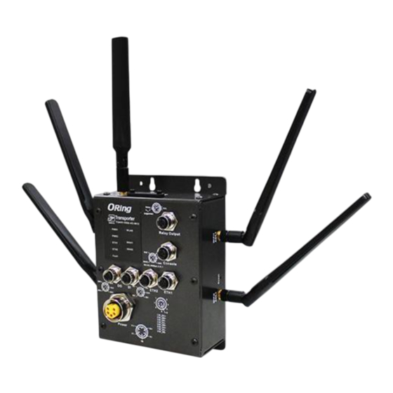
ACCESS POINT ROUTER
Introduction
Designed for industrial and rolling stock wireless applications with two LAN
ports in M12 connectors and EN50155 compliance, the
1062/2062/1662+ series
are IEEE802.11 a/b/g/n routers capable of
providing a fast and effective way to communicate with the Internet over
wired or wireless LANs. The series includes PoE models and 3G/4G models
with GPS functions. The series of devices can be configured to operate in 3
modes of routing function: dynamic/static IP route, PPPoE authentication,
and cellular modem dial up. You can set up WLAN environment to fulfill
demands of various applications rapidly by dialing up cellular modem. With
dual Ethernet ports in switch mode, you can use Daisy Chain to reduce the
usage of Ethernet switch ports. The router also provides VPN capabilities
which create encrypted virtual tunnels on the Internet, allowing remote or
mobile users to connect to the network of your office.
Package Contents
The devices are shipped with the following items. If any of these items is
missing or damaged, please contact your customer service representative for
assistance.
Contents
Pictures
Router
2.4GHz/5GHz Wi-Fi
Antenna
3G or 4G Antenna
CD
QIG
Allen Key
Preparation
Before you begin installing the device, make sure you have all of the package
contents available and a PC with Microsoft Internet Explorer 6.0 or later, for
using web-based system management tools.
Safety & Warnings
Elevated Operating Ambient:
If installed in a closed environment, make sure
the operating ambient temperature is compatible with the maximum
ambient temperature (Tma) specified by the manufacturer.
Reduced Air Flow:
Make sure the amount of air flow required for safe operation
of the equipment is not compromised during installation.
Mechanical Loading:
Make sure the mounting of the equipment is not in a
hazardous condition due to uneven mechanical loading.
Q I G
TGAR+ GPS Series
TGAR+ GPS Series
G
uide
Circuit Overloading: Consideration should be given to the connection of the equipment to
the supply circuit and the effect that overloading of the circuits might have on overcurrent
TGAR-
protection and supply wiring. Appropriate consideration of equipment nameplate ratings
should be used when addressing this concern.
Dimension
Number
1
Panel Layouts
2 (TGAR-1062+/2062+) or
4 (TGAR-1662+)
12
13
1 (TGAR-1062+/1662+) or
2 (TGAR-2062+)
11
TGAR-1062+-GPS-M12
PWR1
WAN
1
PWR2
4
(P.O.E)
ETH1
WLAN
2
1
ETH2
5
3
Fault
9
DO1
DO2
DI1
DO
DI
GND
DO4
DO3
DI4
1
10
Power
V1+
V1-
1
TGAR-1062+-3/4GS-M12
1. PWR status LED
(PW2 with PoE indicator)
2. LAN port status LED
3. Fault status LED
4. WAN status LED
1907-2-29-TGAR+GPS-1.0
125.6
15.0
Relay
N.C.
1A@24VDC
TGAR+ GPS Series
Relay Output
PWR1
WAN
PWR2
(P.O.E)
ETH1
WLAN1
ETH2
WLAN2
RxD
TxD
N.C.
Fault
Console
RSVD
GND
RS-232, 115200bps, 8, N, 1
DO1
DO2
DO
DI
DI1
DI2
ETH2
ETH1
GND
COM
(P.O.E)
DO4
DO3
DI4
DI3
1
2
7
3
6
4
5
8
1 BI_DC+
2 BI_DD+
3 BI_DD-
4 BI_DA-
5 BI_DB+
6 BI_DA+
V1+
V2+
7 BI_DC-
Power
8 BI_DB-
V1-
V2-
R2.5
12.5
R4.0
56.5
19.1
65
86.0
Front Panel
12
13
12
Relay
N.C.
11
Relay
N.C.
11
1A@24VDC
1A@24VDC
6
6
TGAR-2062+-GPS-M12
TGAR-1662+-GPS-M12
Relay Output
Relay Output
PWR1
WAN1
PWR1
1
4
1
PWR2
WAN2
PWR2
(P.O.E)
(P.O.E)
ETH1
WLAN
ETH1
2
2
7
7
RxD
TxD
ETH2
5
RxD
TxD
ETH2
N.C.
3
N.C.
3
Fault
Fault
RSVD
GND
Console
RSVD
GND
Console
RS-232, 115200bps, 8, N, 1
RS-232, 115200bps, 8, N, 1
8
9
8
9
DI2
DO1
DO2
DI1
DI2
DO1
DO2
ETH2
ETH1
DO
DI
ETH2
ETH1
DO
COM
(P.O.E)
GND
COM
(P.O.E)
GND
DI3
1
2
DO4
DO3
DI4
DI3
1
2
DO4
DO3
7
3
7
3
6
4
6
4
5
8
10
5
8
10
1 BI_DC+
1 BI_DC+
2 BI_DD+
2 BI_DD+
3 BI_DD-
3 BI_DD-
4 BI_DA-
4 BI_DA-
5 BI_DB+
5 BI_DB+
6 BI_DA+
6 BI_DA+
7 BI_DC-
7 BI_DC-
V2+
8 BI_DB-
Power
V1+
V2+
8 BI_DB-
Power
V2-
V1-
V2-
14
13
14
12
TGAR-2062+-3/4GS-M12
TGAR-1662+-3/4GS-M12
5. WLAN status LED
9. DI/DO ports
6. Relay output port
10. Power connector
7. Console port
11. 2.4/5GHz Wi-Fi antenna
8. Ethernet LAN ports
12. Cellular antenna connector
(ETH2 with PoE)
13. SIM card slot
14. Ground
Side Panel
1
3
1. 3G/4G Antenna connector
2. Reset button
3. GPS antenna connector
1
2
PRINTED ON RECYCLED PAPER
EN50155 Industrial Wireless LAN
PoE Access Point Router
Top Panel
TGAR-1062+/1662+
TGAR-2062+-3/4GS-M12
-3/4GS-M12
Installation
Wall-mount
The device can be fixed to the wall. Follow the steps below
to install the device on the wall.
Step 1:
Hold the
d
evice upright against the wall
Step 2:
Insert four screws through the large opening of
the keyhole-shaped apertures at the top and bottom of
the unit and fasten the screw to the wall with a screwdriver.
Step 3:
Slide the
d
evice downwards and tighten the four
screws for added stability.
Wiring
For pin assignments of power, console and relay output ports, please refer to the following tables.
Grounding
Grounding and wire routing help limit the effects of noise due to electromagnetic interference
13
(EMI). Run the ground connection from the grounding pin on the power connector to the grounding
surface prior to connecting devices.
Relay
N.C.
1A@24VDC
Power port pinouts
6
Relay Output
WAN
4
The device supports two sets of power supplies and uses the M23 5-pin
WLAN1
7
female connector on the front panel for the dual power inputs.
WLAN2
RxD
TxD
N.C.
5
RSVD
GND
Console
Step 1:
Insert a power cable to the power connector on the device.
RS-232, 115200bps, 8, N, 1
8
Step 2:
Rotate the outer ring of the cable connector until a snug fit is
DI1
DI2
DI
ETH2
ETH1
achieved. Make sure the connection is tight.
COM
(P.O.E)
DI4
DI3
1
2
7
3
6
4
5
8
1 BI_DC+
2 BI_DD+
3 BI_DD-
4 BI_DA-
5 BI_DB+
6 BI_DA+
7 BI_DC-
V1+
V2+
8 BI_DB-
Relay output port pinouts
V1-
V2-
Relay
N.C.
14
1A@24VDC
Network Connection
The AP router has two 10/100/1000 Base-T(X) Ethernet ports. According to the link type, the AP
router uses CAT 3, 4, 5, 5e, UTP cables to connect to any other network device (PCs, servers,
d
evicees, routers, or hubs). Please refer to the following table for cable specifications.
Cable
Type
10Base-T
Cat. 3, 4, 5 100-ohm
UTP 100 m (328 ft)
100Base-TX
Cat. 5 100-ohm UTP
UTP 100 m (328 ft)
1000Base-T
Cat. 5/Cat. 5e 100-ohm UTP UTP 100 m (328 ft)
Version 1.0
Bottom Panel
TGAR-2062+-3/4GS-M12
V1+
V2+
V1-
V2-
DI/DO Port Pinouts
DI
DO
DI1
DI2
DO1
DO2
COM
GND
DI4
DI3
DO4
DO3
Max. Length
Connector
M12
M12
M12
Quick Installation Guide
Advertisement
Table of Contents

Subscribe to Our Youtube Channel
Related Manuals for ORiNG TGAR-1062PLUS-3GS-M12


Summary of Contents for ORiNG TGAR-1062PLUS-3GS-M12
- Page 1 Version 1.0 EN50155 Industrial Wireless LAN EN50155 TGAR+ GPS Series Wireless PoE Access Point Router uick nstallation uide ACCESS POINT ROUTER Introduction Top Panel Bottom Panel Circuit Overloading: Consideration should be given to the connection of the equipment to Designed for industrial and rolling stock wireless applications with two LAN the supply circuit and the effect that overloading of the circuits might have on overcurrent ports in M12 connectors and EN50155 compliance, the TGAR-...
- Page 2 For information on operating the device ORing Industrial Networking Corp. WPA-PSK (256-bit key pre-shared key supported) Encryption Security using ORing’s Open-Vision management utility, please go to ORing website. 802.1X Authentication supported TEL: +886-2-2218-1066 Website: www.oring-networking.com FAX: +886-2-2218-1014 E-mail: support@oring-networking.com...
Need help?
Do you have a question about the TGAR-1062PLUS-3GS-M12 and is the answer not in the manual?
Questions and answers