Advertisement
Quick Links
EN50155
Switch
Q
I
I N D U S T R I A L
uick
nstallation
Introduction
T M
ORing's Transporter
series un-managed Ethernet switches are designed for
industrial applications, such as rolling stock, vehicle, and railway applications.
The
TGXPS-1080-M12-MV
is an un-managed PoE Ethernet switch with
8x10/100/500/1000Base-T(X) P.S.E. which is specifically designed for the
toughest and fully compliant with EN50155 requirement. TGXPS-1080-M12-
MV also supports Power over Ethernet, a system to transmit electrical power,
along with data, to remote devices over standard twisted-pair cable in an
E t h e r n e t n e t w o r k . E a c h
T G X P S - 1 0 8 0 - M 1 2 - M V
8X10/100/500/1000Base-T(X) IEEE 802.3af/at P.S.E. (Power Sourcing
Equipment) ports, but the PoE total power budget is 60Watts Max. P.S.E. is a
device (switch or hub for instance) that will provide power in a PoE setup.
TGXPS-1080-M12-MV EN50155 Ethernet switch use M12 connectors to
ensure tight, robust connections, and guarantee reliable operation against
environmental disturbances, such as vibration and shock. In addition, the wide
o
operating temperature range from -40 C to 75 C can satisfy most of operating
environment. Therefore, the switch is one of the most reliable choices for
rolling stock and highly-managed PoE Ethernet application.
While installing in the train,
TGXPS-1080-M12-MV
monitoring and Entertainment service due to its high-speed Gigabit Ethernet
connection and PoE capability. Devices connected will be IP camera or CCTV
for the use of train surveillance. As an unmanaged Ethernet Switch, TGXPS-
1080-M12-MV is not able and will not be used for any control related
application. Its main function is simply forwarding the Ethernet packet from one
Ethernet based device to another Ethernet device which are all connected to
the Switch.
Package Contents
The device is shipped with the following items. If any of these items is
missing or damaged, please contact your customer service representative
for assistance.
Contents
Pictures
TGXPS-1080-M12-MV or
TGXPS-1080-M12-BP2-MV
QIG
Preparation
Before you begin installing the switch, make sure you have all of the package
contents available.
Safety & Warnings
Elevated Operating Ambient: If installed in a closed environment, make
sure the operating ambient temperature is compatible with the maximum
ambient temperature (Tma) specified by the manufacturer.
Reduced Air Flow: Make sure the amount of air flow required for safe
operation of the equipment is not compromised during installation.
Mechanical Loading: Make sure the mounting of the equipment is not in a
hazardous condition due to uneven mechanical loading.
Circuit Overloading:
Consideration should be given to the connection of the
equipment to the supply circuit and the effect that overloading of the circuits
might have on overcurrent protection and supply wiring. Appropriate
consideration of equipment nameplate ratings should be used when
Q I G
TGXPS-1080-M12-MV Series
TGXPS-1080-M12-MV Series
G
uide
Dimension
s w i t c h h a s
o
is mainly used for in-train
65.0
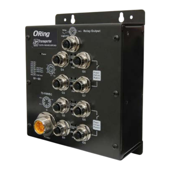
Panel Layouts
Front View
Relay
3A@24VDC
TGXPS-1080-M12-BP2-MV
1
Power
1 BI_DC+
2 BI_DD+
1
2
G4
3 BI_DD-
Number
4 BI_DA- / PoE Vout+
7
5 BI_DB+ / PoE Vout-
6 BI_DA+ / PoE Vout+
6
4
7 BI_DC-
5
8 BI_DB- / PoE Vout-
8
G1~ G8
G3
72~110VDC
N.C.
V+
1
N.C.
V-
G2
2
G1
Power
1
6
Installation
Wall-mount
The device can be fixed to the wall. Follow the steps below to install the device on the wall.
Step 1: Hold the
Step 2: Insert four screws through the large opening of the keyhole-shaped apertures at the
top and bottom of the unit and fasten the screw to the wall with a screwdriver.
Step 3: Slide the
1907-200-T1080MVXX1-FX010
Unit =mm (Tolerance ±0.5mm)
150.0
111.0
81.5
Ø5.0
Ø4.0
Relay
N.C.
Relay Output
Ø8.00
3A@24VDC
TGXPS-1080-M12-BP2-MV
Power
10/100/1G
500M
LNK/ACT
1 BI_DC+
PoE
2 BI_DD+
1
2
3 BI_DD-
G4
G8
Power
Failure
4 BI_DA- / PoE Vout+
7
5 BI_DB+ / PoE Vout-
Bypass
6 BI_DA+ / PoE Vout+
6
4
7 BI_DC-
5
8
8 BI_DB- / PoE Vout-
500M
10/100/1G
G1~ G8
LNK/ACT
PoE
G3
G7
72~110VDC
N.C.
V+
10/100/1G
500M
N.C.
V-
LNK/ACT
PoE
G2
G6
Power
Failure
Bypass
10/100/1G
500M
LNK/ACT
PoE
G1
G5
Power
1. Power status LED
N.C.
Relay Output
2. Power input port
3
3. Relay output port
4. LNK/ACT & Speed LED for Gigabit ports
10/100/1G
500M
LNK/ACT
(1Gbps/10Mbps/100Mbps)
PoE
G8
Power
Failure
5. LNK/ACT & Speed LED for Gigabit ports (500Mbps)
Bypass
10/100/1G
500M
6. Gigabit Ethernet ports
LNK/ACT
(G5-G8 of TGXPS-1080-M12-BP2-MV are bypass ports)
PoE
G7
4
7. PoE status LED
10/100/1G
500M
5
LNK/ACT
PoE
G6
Power
Failure
Bypass
10/100/1G
500M
LNK/ACT
PoE
G5
7
6
d
evice upright against the wall
d
evice downwards and tighten the four screws for added stability.
PRINTED ON RECYCLED PAPER
EN50155 8-port unmanaged
Gigabit PoE Ethernet switch
Instead of screwing the screws in all the way, it is advised
to leave a space of about 2mm to allow room for sliding
the switch between the wall and the screws.
Wiring
For pin assignments of power and relay output ports, please refer to the following tables.
Grounding
Grounding and wire routing help limit the effects of noise due to electromagnetic interference
(EMI). Run the ground connection from the grounding pin on the power connector to the grounding
surface prior to connecting devices.
Power port pinouts
The device supports one set of power supplies and uses the 7/8 inch
M23 5-pin male connector on the front panel for the power input.
Step 1: Insert a power cable to the power connector on the device.
Step 2: Rotate the outer ring of the cable connector until a snug fit is
achieved. Make sure the connection is tight.
Relay output port pinouts
The switch uses the M12 A-coded 5-pin female connector
on the front panel for relay output. Use a power cord with an
M12 A-coded 5-pin male connector to connect the relay.
The relay contacts will detect power off event to trigger
warning system.
Network Connection
The device provides Ethernet ports in M12 connector type. According to the link type, the switch
uses CAT 3, 4, 5,5e UTP cables to connect to any other network devices (PCs, servers, switches,
routers, or hubs). Please refer to the following table for cable specifications.
Cable
Type
Max. Length
Connector
10BASE-T
Cat. 3, 4, 5 100-ohm
UTP 100 m (328 ft)
M12 A-coding connector
100BASE-TX
Cat. 5 100-ohm UTP
UTP 100 m (328 ft)
M12 A-coding connector
1000BASE-T
Cat. 5/Cat. 5e 100-ohm UTP
UTP 100 m (328ft)
M12 A-coding connector
For pin assignments of the LAN ports, please refer to the following tables.
10/100/1000Base-T(X) M12 port
1
2
7
3
PIN
Definition
6
4
5
8
1
BI_DC+
2
BI_DD+
3
BI_DD-
4
BI_DA- / PoE Vout+
5
BI_DB+ / PoE Vout-
6
BI_DA+ / PoE Vout+
7
BI_DC-
8
BI_DB- / PoE Vout-
Quick Installation Guide
Version 1.0
N.C.
V+
N.C.
V-
Relay
N.C.
3A@24VDC
Advertisement

Subscribe to Our Youtube Channel
Related Manuals for ORiNG TGXPS-1080-M12-MV Series


Summary of Contents for ORiNG TGXPS-1080-M12-MV Series
- Page 1 Version 1.0 EN50155 EN50155 8-port unmanaged Switch TGXPS-1080-M12-MV Series I N D U S T R I A L Gigabit PoE Ethernet switch uick nstallation uide Introduction Dimension Instead of screwing the screws in all the way, it is advised...
- Page 2 -40 to 75 C (-40 to 167 F) Operating Humidity 5% to 95% Non-condensing Copyright© 2019 ORing Regulatory Approvals All rights reserved. ORing Industrial Networking Corp. TEL: +886-2-2218-1066 Website: www.oringnet.com FAX: +886-2-2218-1014 E-mail: support@oringnet.com Q I G Q I G...
Need help?
Do you have a question about the TGXPS-1080-M12-MV Series and is the answer not in the manual?
Questions and answers