Vivo STAND-TV09 Instruction Manual
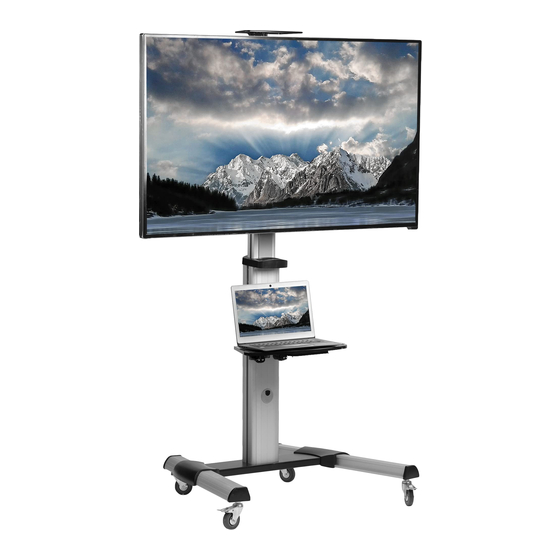
Silver mobile tv cart
Hide thumbs
Also See for STAND-TV09:
- Instruction manual (6 pages) ,
- Instruction manual (8 pages) ,
- Instruction manual (12 pages)
Table of Contents
Advertisement
Quick Links
Silver Mobile TV Cart
Instruction Manual
SKU: STAND-TV09
Scan the QR code with your mobile device or follow the link
for helpful videos and specifications related to this product.
https://vivo-us.com/products/stand-tv09
GET IN TOUCH | Monday-Friday from 7:00am-7:00pm CST
help@vivo-us.com
www.vivo-us.com
Chat live with an agent!
309-278-5303
Advertisement
Table of Contents

Subscribe to Our Youtube Channel
Related Manuals for Vivo STAND-TV09


Summary of Contents for Vivo STAND-TV09
- Page 1 Silver Mobile TV Cart Instruction Manual SKU: STAND-TV09 Scan the QR code with your mobile device or follow the link for helpful videos and specifications related to this product. https://vivo-us.com/products/stand-tv09 GET IN TOUCH | Monday-Friday from 7:00am-7:00pm CST help@vivo-us.com www.vivo-us.com...
- Page 2 WARNING! If you do not understand these directions, or if you have any doubts about the safety of the installation, please call a qualified technician. Check carefully to make sure there are no missing or defective parts. Improper installation may cause damage or serious injury. Do not use this product for any purpose that is not explicitly specified in this manual.
- Page 3 TOOLS NEEDED 11lbs 11lbs (5kg) (5kg) Phillips Screwdriver CAMERA ASSEMBLY STEPS STEP 1 Insert the base (A) into the left leg (B). Align the mounting holes and secure with M6x16 bolts (Q). Repeat this step for the right leg (C). Adjust caster height if needed by loosening the nut with the wrench (Z).
- Page 4 STEP 3 Attach the support plate (F) to the column (J) with M6x14 bolts (U). Tighten bolts using a screwdriver. Place left and right covers (D) and (E) over the base of the stand. STEP 4 Insert the washers (P) into the back of universal plate (G) along the plate rails.
- Page 5 STEP 4 (Continued) OPTION B: Curved Back Screen Choose the appropriate bolts, washers and spacers (if necessary) according to the type of screen. Tighten all bolts but do not over tighten. Screw the adapter brackets onto the display. STEP 5 Hang the universal plate (G) onto the support plate (F), and secure with M5x8 bolts (X).
- Page 6 STEP 7 Run cables through cable management slots. STEP 8 Attach the camera shelf (N) to the connecting plate (M) using M4x6 flat head bolts (S). Tighten M4x6 dome head screws (T) into back of camera shelf and connecting plate. STEP 9 Attach the connecting plate (M) to the column (J) at the desired height using M6x25 bolts (R).
- Page 7 STEP 10 OPTION A: Landscape View To rotate from portrait to landscape view, remove the two screws from the back of support plate (F). Turn the display, and secure with the previously removed screws. Install at least two screws diagonally to secure the display.
- Page 8 - 92% within < 3hr www.vivo-us.com : < 15 M AVG. RESOLUTION TIME (within office hrs) Chat live with an agent! : 5M 4S 309-278-5303 AVG. RESOLUTION TIME (within office hrs) FOR MORE VIVO PRODUCTS, CHECK OUT OUR WEBSITE AT: www.vivo-us.com...
Need help?
Do you have a question about the STAND-TV09 and is the answer not in the manual?
Questions and answers