NSK Primado2 Operation Manual
Total surgical system
Hide thumbs
Also See for Primado2:
- Operation manual (301 pages) ,
- Reprocessing manual (152 pages) ,
- Operation manual (5 pages)
Table of Contents
Advertisement
Advertisement
Table of Contents

Related Manuals for NSK Primado2


Summary of Contents for NSK Primado2
- Page 1 Primado2 OM-SE0028E 002...
-
Page 2: Table Of Contents
This product is a surgical system used for bone operations (removal, cutting, perforation and formation), or cutting implants. Prior to using this system, read the Operation Manual thoroughly in order to understand the instructions and directions for use, how to handle the equipment and maintenance matters, so that you can use this system properly for many years to come. - Page 3 Before use, read carefully the Operation Manual of the Motor and the Attachments/Handpieces. Intended Use The Primado 2 is an AC-electrically powered total surgical system that is intended for cutting, drilling, sawing, and otherwise manipulating soft tissue, hard tissue, bone, bone cement, prosthesis, implant, and other bone related tissue in a variety of surgical procedures, including but not limited to Cranial(Craniofacial/Maxillofacial), ENT, Endoscopic/Arthroscopic, Neuro, Orthopedic, Spinal, and General surgical procedures.
-
Page 4: Component Names
P200-SMH Primado2 Slim Motor client’s specific needs. P200-SMH-HS Primado2 Slim Motor (Motor with Hand Control) 10 P200-BMH Primado2 Micro Bone Saw Motor 11 P200-BMH-HS Primado2 Micro Bone Saw Motor (Motor with Hand Control) 12 P200-WPD Primado2 Wire Pin Driver... -
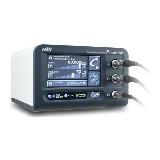
Page 5: Part Names
Part Names 2-1 Control Unit Front Side of the Control Unit 1) Front Panel 2) Motor Connector A 3) Motor Connector B 4) LCD Touch Panel 5) Foot Control Connector Right-hand Side of the Control Unit 6) Irrigation Pump 7) Guide Parts 8) Roller 9) Knob Back Side of the Control Unit... - Page 6 2-3 Motor P200-HMH, P200-SMH, P200-BMH P200-HMH-HS, P200-SMH-HS, P200-BMH-HS (Motor with Hand Contol) 4) 4) 1) Hand Switch* 2) Adjustable Lever* 3) Safety Lock* 4) Motor Cord Plug *Motor with Hand Control only. P200-WPD 5) 5) 1) Trigger (Upper) (A) 2) Safety Lock 3) Trigger (Lower) (B) 4) Mounting/Removal Button 5) Motor Cord Plug...
- Page 7 2-5 Buttons & Icons Icon Name Descriptions Motor Select Button A Selects the Motor which is connected to Motor Connector A. If the Motor is not connected, “Disconnection” is displayed. Motor Select Button B Selects the Motor which is connected to Motor Connector B.
- Page 8 Icon Name Descriptions Control Unit Set Up Button Displays the “Control Unit Set Up” screen. Motor Set Up Button Displays the “Motor Set Up” screen. Attachment Set Up Button Displays the “Attachment Set Up” screen. Foot Control Set Up Button Displays “Foot Control Set Up”...
- Page 9 Icon Name Descriptions Acceleration Area The acceleration time for the Motor to reach its maximum rotational speed can be adjusted by the UP/DOWN Button (10%~100%). Brake Area The braking time for the Motor to stop can be adjusted by the UP/DOWN Button (10%~100%). Torque Area The torque of the Motor can be adjusted by the UP/DOWN Button (30%~100%).
- Page 10 Icon Name Descriptions Foot Control Button Displays the “Foot Control Set Up” screen. (Blue) (Only for the Multi Foot Control) Foot Control Button (Silver) Foot Control Button (Green) (Only for the Multi Foot Control) Foot Control Pedal ON/OFF Select Turns ON/OFF the operation of the Foot Control by the Foot Control.
- Page 11 2-6 Flow Chart of the LCD Touch Panel HOME Screen Main Panel Speed Adjustment Irrigation Volume Adjustment Rotation Mode Switch Priming Motor Switch Sub Panel Control Unit Background Brightness Mini Panel Option Set Up Set Up Adjustment Volume Adjustment Language Set Up English Information German...
-
Page 12: How To Connect Each Component
How to Connect Each Component Do not remove the Power Cord or Motor Cord by holding the cord portion or failure might occur. Hold the plug. CAUTION Connect or disconnect the Power Cord or Motor Cord only after turning OFF the Power Switch. Otherwise, personal injury may result caused by an unexpected rotation. - Page 13 3-3 Connection of the Motor By matching the mark on the Motor Cord Plug and the mark on the Motor Connector (A or B) at the front of the Control Unit, plug the Motor into the Connector all the way. Mark Mark There are two Motor Connectors.
- Page 14 P200-BMH and P200-BMH-HS Attachments/Handpieces Alignment Hole Alignment Pin <Mounting> 1) Push the Attachment/Handpiece into the Motor straight. 2) Turn the Attachment/Handpiece rightward or leftward so that the Alignment Pin of the Motor matches the hole of the Attachment/Handpiece with a clicking sound to Motor CLOSE connect firmly.
- Page 15 Prior to inserting the Irrigation Tube into the Irrigation Pump, confirm that there is no foreign substance in the roller portion. When closing the Pump Cover, do not force the Knob excessively and be careful not to get your fingers caught. Use only Irrigation Tube (Order Code: PD-IT-S) recommended by NSK. Non-NSK-genuine irrigation tubes could cause failure.
-
Page 16: Check Before Operation
Check before Operation Follow the check list below, before use. If any abnormalities are found, stop using the product immediately and contact your dealer. 4-1 Control Unit 1) Check for any abnormalities or damage on the outer surface. 2) Check that the Power Cord can be securely connected to the Control Unit and the medical-use outlet. 3) Turn the power ON and check for any abnormalities on the LCD display. - Page 17 5-2 Operation of the Main Panel 5-2-1 How to set the rotational speed and irrigation volume Push the UP/DOWN Button or move the Track Bar to set the speed or volume. (The Track Bar moves to the position which you have touched, within the adjustment area. Since it is rather difficult to accomplish a fine setting, use the UP/DOWN button for fine tuning.) Speed Adjustment Area...
- Page 18 5-3 How to operate the Motor This can be done in three ways: by the Motor with Hand Control, the Primado2 Wire Pin Driver or the Foot Control. The Motor with Hand Control and the Primado2 Wire Pin Driver can also be operated by the Foot Control. Connect it with CAUTION the Foot Control and depress the Pedal.
- Page 19 When Using the Foot Control (FC-73, FC-74) 1) When depressing the Pedal of the Foot Control, the Motor starts to operate. When depressing the Pedal or releasing it, a short alarm sounds. 2) In the Reverse Mode, the Bur starts rotating in reverse. During this reverse rotation, the alarm continues to sound.
-
Page 20: Option Set Up
Option Set Up It is possible to change the setting of the Control Unit and Motor by setting up the options. The components which can be set up are as follows: 1) Touch the Option Set Up Button in the Mini Panel in the HOME Option screen to display the Option Set Up screen. - Page 21 6-1-1 Adjusting the background brightness and volume The background brightness and volume level can be adjusted by either touching the UP/DOWN Button, or by moving the Track Bar to the desired level (Touch a position within the Adjustment Area to move the Track Bar to that position. For fine tuning, use the UP/DOWN Button).
- Page 22 6-2 Adjusting the Motor Touch the Motor Set Up Button in the Option Set Up screen to display the Motor Set Up screen. Motor Set Up Screen Acceleration Area Brake Area Torque Area Factory Default Button Oscillating Turns Area Motor Select Button Fig.
- Page 23 Attachment Set Up Screen Since the Attachment/Handpieces available differ depending on the type of the Motor used, the Attachment Set Up screen matching the connected Motor is displayed. For P200-HMH For P200-SMH For P200-BMH For P200-WPD Fig. 36 Compatible Attachments/Handpieces Motor Attachment/Handpiece Compatible Attachments/Handpieces...
- Page 24 6-4 Setting Up the Foot Control 1) Touch the Foot Control Set Up Button in the Option Set Up screen to display the Foot Control Set Up screen. Foot Control Set Up Screen Multi Foot Control Single Foot Control Fig. 37 2) Touch the Foot Control Button (Multi Foot Control: blue, silver and green buttons ;...
-
Page 25: Fuse Replacement
2) Replace the fuses (2 pcs) with a new one and push the Fuse Box into the Inlet Box until you hear a clicking sound. Fuse Box Do not use any type of fuse other than ones NSK recommends. Otherwise, CAUTION failure might occur. -
Page 26: Error Codes
8-2-3 Washing and disinfecting The Motor can be washed via Thermo Disinfector. If a Thermo-Disinfector is not available, proceed to 8-2-4 Sterilization below. The following conditions are recommended for Thermo Disinfector: (It is recommended to use a thermo disinfector compatible with ISO 15883) a. - Page 27 Error codes Error contents Causes Checks and measures Error of the Control Abnormality or failure of the Turn ON the power source again. If the Control Unit operates normally, internal memory of the Control there is no problem. Unit. Unit. Fasten the Twist Collet of the Attachment to lock the Bur.
- Page 28 Error codes Error contents Causes Checks and measures Error of the Motor Poor connection of the Motor Fasten the Twist Collet of the Attachment to lock the Bur. If the Motor Handpiece. Handpiece works normally, there is no problem. Handpiece. Re-connect the Motor Handpiece to the Control Unit.
- Page 29 Error codes Error contents Causes Checks and measures Error of the Irrigation Failure of the Irrigation Pump Turn ON the power source again. If the same error code is displayed, (excessive voltage). the Irrigation Pump might be damaged. Contact your dealer for repair Pump.
-
Page 30: Troubleshooting
Troubleshooting If you are suspecting any faults, check the following once again prior to asking for repair work. If none of these cases is applicable or if the situation does not improve despite your efforts or measures, the damage could be serious; call your dealer to fix the problem. <Control Unit>... - Page 31 <Motor (without Hand Control)> Symptoms Causes/Points of checking Countermeasures After inserting the Cutting Accessories, fasten the No rotation after a Cutting The Twist Collet on the Attachment/Handpiece is Accessories has been OPEN. Twist Collet. Turn it in the direction of ‘ ’ attached.
-
Page 32: Specifications
Specifications <Control Unit> Model P200-CU-120 Power source AC 120V 50/60 Hz Electricity consumption 65 VA Maximum feed rate of Irrigation Pump 75 ml/min Dimensions W278×D268×H160 mm Weight 6.9Kg Length of Power Cord 3.6 m <Motor> Model P200-HMH P200-SMH P200-BMH P200-WPD P200-HMH-HS P200-SMH-HS P200-BMH-HS... -
Page 33: Disposing Product
Disposing Product In order to avoid the health risks of operators handling the disposal of medical equipment, as well as the risks of environmental contamination caused thereof, a surgeon is required to confirm the equipment is sterile. Ask specialist firms who are licensed to dispose of specially controlled industrial wastes, to dispose the product for you. -
Page 34: Emc Information
To assess the electromagnetic environment due to fixed RF transmitters, an electromagnetic site survey should be considered. If the measured field strength in the location in which the Primado2 is used exceeds the applicable RF compliance level above, the Primado2 should be observed to verify normal operation. If abnormal performance is observed, additional measures may be necessary, such as reorienting or relocating the Primado2. - Page 35 EN/IEC61000-4-3 Recommended separation distances between portable and mobile RF communications equipment and the Primado2. The Primado 2 is intended for use in an electromagnetic environment in which radiated RF disturbances are control LCD. The customer or the user of the Primado 2 can help prevent electromagnetic interference by maintaining a minimum distance between portable and mobile RF communications equipment (transmitters) and the Primado 2 as recommended below, according to the maximum output power of the communications equipment.
- Page 36 Please read this Operation Manual carefully before use, and file for Specification are subject to change without notice. future reference. 2019.02.01 001...
Need help?
Do you have a question about the Primado2 and is the answer not in the manual?
Questions and answers