Table of Contents
Advertisement
Original Operatrion Manual
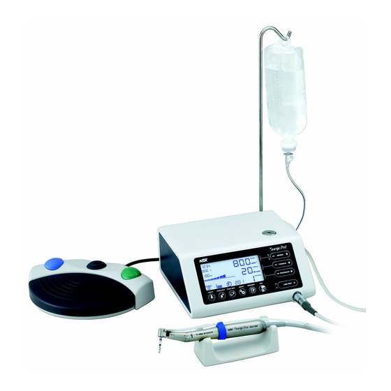
Thank you for purchasing the NSK Surgic Pro series surgical unit.
We recommend that prior to use, you carefully read this document regarding instructions for use, handling method, or
maintenance check so that you can carry on using the unit in the future. In addition, keep this operation manual in a place
where a user can refer to it at any given time.
◆ Intended to Use
Surgic Pro series is intended for use in dental oral surgery and surgical procedures by qualified personnel.
1.
2.
3.
4.
5.
6.
7.
8.
9.
10.
11.
12.
13.
14.
15.
16.
◆ Classification of equipment
• Type of protection against electric shock :
- Class l equipment
• Degree of protection against electric shock :
- Type BF applied part
• Method of sterilization or disinfection recommended by the manufacture :
- See 11. Sterilization
• Degree of protection against ingress of water as detailed in the current edition of IEC 60529 :
- Foot Control: IPX8 (Protected against the effects of continuous immersion in water)
• Degree of safety of application in the presence of a flammable anesthetic mixture with air or with oxygen or nitrous
oxide :
- Foot Control: Category AP Equipment
• Mode of operation :
- Intermittent operation
Contents
1
English
2
4
5
7
10
12
16
16
18
18
19
20
20
20
21
21
Advertisement
Table of Contents

Related Manuals for NSK Surgic Pro+


Summary of Contents for NSK Surgic Pro+
-
Page 1: Table Of Contents
Original Operatrion Manual English Thank you for purchasing the NSK Surgic Pro series surgical unit. We recommend that prior to use, you carefully read this document regarding instructions for use, handling method, or maintenance check so that you can carry on using the unit in the future. In addition, keep this operation manual in a place where a user can refer to it at any given time. -
Page 2: Safety Precautions Prior To Use
Real torque value may not otherwise be correctly displayed. To guarantee handpiece torque accuracy, that matches the monitor display system, USE ONLY the NSK contra angle handpieces listed on “12. Contra Angle Handpieces and Accessories”. When other handpice had connected, it may not output accurate torque which indicated on handpiece. - Page 3 • Turn off the Main Power Switch after each use. • For service requirements and spare parts contact dealer. • Use of NSK genuine pre-sterilized, disposable Irrigation Tube is recommended. • Total recording time is about 100 minutes. (Surgic Pro + ) •...
-
Page 4: Package Contents
2. Package Contents *Figure shows Optic Motor and Optic Handpiece Item Item Description Quantity Description Quantity AC Power Cord Handpiece Stand Foot Controller with Cord (2m) Internal Irrigation Nozzle Control Unit Nozzle Holder Irrigation Tube Cleaning Wire Coolant Solution Hanger Post Calibration Bur Optic Handpiece / Non-Optic Handpiece * E-type Spray Nozzle... -
Page 5: Control Unit And Foot Control
3. Control Unit and Foot Control Coolant Solution Hanger Post Holder USB flash drive Socket Calibration Load Irrigation Pump (1) Light Key (7) SPEED Key (2) Coolant Key Main Power Switch (8) TORQUE Key (3) FWD/REV Key AC Power Cord (9) PROGRAM Key Connector socket (4) GEAR Key... - Page 6 3-2 LCD display on the Control Unit Console (A) Clock Display (E) USB flash drive (B) SPEED (G) TORQUE (C) IMPLANT SYSTEM (D) Memory Time (F) TORQUE Graph (H) Light Level ( I ) Coolant Level (J) FWD/REV Direction (K) GEAR Ratio (L) PROGRAM Number Clock Display (Surgic Pro + ONLY) Clock display.
-
Page 7: Installation
3-3 Foot Control Foot Control Cord and Plug (b) PRG (Program) Button (a) Coolant Solution Flow (d) Forward/Reverse Button Volume Button (c) Speed Control Pedal Coolant Solution Flow Volume Button Use to select 6 levels of coolant solution flow from 0 to 5; each level may be increased by one step pressing this button. - Page 8 4-2 Connecting the Handpiece CAUTION When using the Optic Surgic Pro micromotor (SGL70M), USE ONLY Optic contra-angle handpieces. Non Optic handpieces may not precisely connect to the micromotor and it may malfunction when the micromotor is under load. Push the handpiece on to the motor taking care to keep it in alignment.
- Page 9 CAUTION • Make sure that the tube is securely set on the rollers when closing the Pump Cover. If the tube is not correctly positioned on the Rollers and the cover is closed, the tube could be cut or sheared. (Fig.5) •...
-
Page 10: Setting
4-8 Compatibility check of Internal Irrigation Nozzle/Drill Internal irrigation nozzles accompanied with this product; is not necessarily fitted into all the drills on the market. Follow the instructions given below for confirmation prior to use. Failure to do so or to fit the Internal Irrigation Nozzle into drills may cause a leakage of saline solution, which will result in problems such as rust or sudden stop of equipment during use. -
Page 11: Factory Settings
NOTICE • Set the Clock before you use this system. • If the clock display does not appear or is shown as “- - : - -” the internal batteries may have run out. Contact the retailer where device was purchased. •... -
Page 12: Operation
6. Operation 6-1 Programming the Micromotor Operation The Control Unit can memorize 8 programs. Each program includes the following functions which will be automatically performed when the appropriate program number is selected. Gear ratio of contra angle handpieces Speed Power Switch Direction of rotation Symbol Mark Torque upper limit... - Page 13 ONLY the 20:1 reduction handpiece listed on “12. Contra Angle Handpieces and Accessories”. • Micro saw handpiece should not be calibrated. • Calibration should be performed only on NSK handpiece. 6-3-1 Calibration preparation Attach Gear Ratio (Reduction Ratio) 20:1 handpiece to the motor.
- Page 14 CAUTION During a process, it is important to hold the Calibration Bur vertically without applying any forcible power. Making the Calibration Bur tilt or pressing it may cause a loss in accuracy. Calibration fail example • Extreme gear abrasion and mechanical loss can exceed the control limits. Correct data cannot be obtained during calibration cycle and the calibration will fail.
- Page 15 NOTICE A BMP file can only be created only when Gear Ratio is 20:1 and the number of rotations is 50min or less. *BMP File Time Torque Irrigation Volume Rotation Speed Gear Ratio Program Number Date Torque Set torque index Time CAUTION •...
-
Page 16: Protection Circuit
7. Protection Circuit An electronic circuit breaker automatically functions to protect the motor and the Control Unit if the motor is ever overloaded. Power supply to the motor will automatically be terminated an Error code will be displayed on the Control Unit. - Page 17 The Irrigation tube is incorrectly Check the Irrigation tube. Pump excess voltage. fitted and loading the pump roller. If an Error Code is displayed even when the Pump excess current. The pump fails. Irrigation tube is normal, request repair. Check the connection state of the connector. Connection failure of the connector.
-
Page 18: Fuse Replacement
9. Fuse Replacement If the Control Unit does not function, check the fuses (Fuse Box lock located on the rear of the Control Unit). To access the Fuse, use a pointed tool push on the fuse locking latch and the drawer will spring open. -
Page 19: Sterilization
* EN13060/EN ISO17665-1 recommends autoclaving for 3 minutes (minimum holding time) at 134°C or 15 minutes(minimum holding time) at 121°C.minutes(minimum holding time) at 121°C. NSK recommends Class B sterilization. CAUTION • Clean and lubricate the handpiece before autoclaving. Autoclaving a handpiece stained with blood or debris could cause damage to the handpiece. -
Page 20: Contra Angle Handpieces And Accessories
12. Contra Angle Handpieces and Accessories Listed below are the contra angle handpieces which should be used with the Surgic Pro micromotor to guarantee torque accuracy. Order Code Description Remarks C1003 X-SG20L Optic surgial handpiece. C1010 SG20 Non-optic surgial handpiece. C1068 X-DSG20L Optic dismantling surgial handpiece. -
Page 21: Symbols
15. Symbols TUV Rhineland of North America is a Nationally Recognized Testing Laboratory (NRTL) in the United States and is accredited by the Standards Council of Canada to certify electro-medical products with Canadian National Standards. This product is designed not to become the ignition source in air and flammable anesthetic gas. The EU directive 93/42/EEC was applied in the design and production of this medical device. - Page 22 Guidance and manufacturer's declaration - electromagnetic immunity Surgic Pro series is intended for use in the electromagnetic environment specified below. The customer or the user of the Surgic Pro series should assure that it is used in such an environment. Immunity test IEC/EN60601 test level Compliance level...
Need help?
Do you have a question about the Surgic Pro+ and is the answer not in the manual?
Questions and answers