
Related Manuals for Afag NVD 3 Series


Summary of Contents for Afag NVD 3 Series
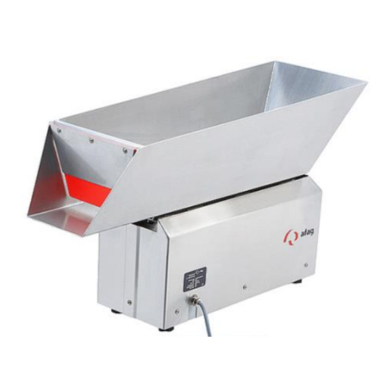
- Page 1 Vibratory hopper unit NVD 3 / NVD 4 Translation of operating and installation instructions Copyright by Afag GmbH...
- Page 2 This operation instruction applies to: Bestellnummer NVD3/5 230V/50Hz 50439542 NVD3/5 5,0 Liters NVD3/5 115V/60Hz 50439547 NVD4/10 230V/50Hz 50439543 NVD4/10 10,0 Liters NVD4/10 115V/60Hz 50439548 NVD4/15 230V/50Hz 50439544 NVD4/15 15,0 Liters NVD4/15 115V/60Hz 50439549 NVD4/20 230V/50Hz 50439545 NVD4/20 20,0 Liters NVD4/20 115V/60Hz 50439550 NVD4/40 230V/50Hz 50439546...
-
Page 3: Table Of Contents
Table of contents: Safety instructions ....................4 Notes on symbols and instructions ......................4 Basic safety information ..........................5 Intended use ..............................5 Notes for Pacemakers and Defibrillators ..................... 6 Description of the device ..................7 General ................................ 7 Functional description ..........................7 Technical Data ............................. -
Page 4: Safety Instructions
1 Safety instructions 1.1 Notes on symbols and instructions Symbols: Assembly and commissioning must be carried out by qualified per- sonnel only and according to these operating instructions. Please observe the meaning of the following symbols and notes. They are grouped into risk levels and classified according to ISO 3864-2. -
Page 5: Basic Safety Information
1.2 Basic safety information This operating manual provides the basis for the safe use and operation of the vibrato- ry feeder. This operating manual and, in particular, the included safety instructions have to be observed by all individuals working with and on the vibratory hopper. In addition, all rules and regulations regarding the accident prevention applicable for the site of operation are to be complied with. -
Page 6: Notes For Pacemakers And Defibrillators
1.4 Notes for Pacemakers and Defibrillators Afag vibration conveyors are tested in accordance with regulation 15 of the German Statutory Accident Insurance Association [Deutsche Gesetzliche Unfallversicherung, DGUV] (previously BGV B11 of German Accident Prevention Regulations). The permissible values of exposure area 2 are not exceeded, therefore no measures are required pursuant to Section 4 (2) of the DGUV regulation 15. -
Page 7: Description Of The Device
2 Description of the device 2.1 General In combination with a dosing channel, the vibratory hopper units are used to store bulk material. The material is moved by vibrations. Parts are moved by micro throws in the feeding direction. 2.2 Functional description The NVD is a unit which transforms magnetic oscillations in order to use the feeding of work pieces. -
Page 8: Technical Data
The magnet, connected to the base, creates a force which attracts reps. releases the armature (Anchor bolt) dependent on the oscillation frequency of the power supply. As the armature (Anchor bolt) is also connected to the vibrating plate, this also makes the same pulsating movement. - Page 9 Table 1: Technical Data Description NVD3/5 NVD4/10 NVD4/15 NVD4/20 NVD4/40 Channel volume 10,0 15,0 20,0 40,0 Dimensions [mm] 1000 [mm] [mm] 444,5 [mm] 266,5 347,2 400,5 [mm] [mm] [mm] [mm] [mm] 162,5 213,5 [mm] [mm] [mm] Operating voltage 230 / 115 Mains frequency 50 / 60 Coil resistance...
-
Page 10: Assembly Instructions
3 Assembly instructions 3.1 Transport WARNING Improper use of transport means (industrial trucks, cranes, tech- nical aids, sling gear etc.) may lead to bruises and other injuries. Required behaviour: ▪ Observe and follow the transport and maintenance instruc- tions ▪ Proper use of transport means CAUTION During transport, the NVD must only be held by the base. -
Page 11: Power Supply
3.3 Power supply WARNING ▪ Any work on the electrical supply may only be performed by trained, authorised, qualified personnel! ▪ The power supply must be protected by an FI switch (pro- vided by the customer). ▪ The bowl feeder may only be operated with the power sup- ply specified on the name plate. -
Page 12: Operating Instructions
4 Operating instructions 4.1 Standard operation No further settings are required for standard operation mode once the controller is switched on. The only thing required for an uninterrupted operation is the re-filling of the dosing channel. 4.2 Adjustments and settings of the NVD Basically the NVD and channel are adjusted in the standard configuration. -
Page 13: Setting The Distance Between The Vibrating Plate And The Support Base
CAUTION The casing must be replaced after each procedure! 4.3 Setting the distance between the vibrating plate and the support base This setting is only necessary when: all spring packages have been exchanged or re-assembled the NVD has been dismantled WARNING Unplug the power cable, before proceeding with further actions! 1. -
Page 14: Torques
4.4 Torques Tightening torques M in Nm for shank screws with metric ISO control threads and head supports according to DIN 912 or DIN 931: Tightening torques M in Nm Screw Strength class 8.8 Strength class 10.9 Strength class 12.9 14,0 16,5 (M7) -
Page 15: Maintenance Instructions
▪ Before removing the casing, unplug the power cable! Interruptions caused by defective components must be repaired by replacing the de- fective component, only. NOTE Defective components must only be replaced by Afag original spare parts. R06.0 16/05/2019 Page 15... - Page 16 Bowl feeder does not run after switch on Cause of fault: Fault repair Plug not connected Connect plug Connecting cable between NVD and Connect plug controller not plugged in Regulator on controller set to „0“ Turn regulator to position Defective fuse in control unit Replace fuse Bowl feeder lacks performance after operating for a certain length of time Cause of fault:...
-
Page 17: Cleaning
5.2 Cleaning Coating: Detergent: Cleaning method: hard-anodised Inox Alcool or spirit Ultrasonic bath polished Metaline Soap wather clean with a damp cloth, let it dry Habasit light green neither vacuum cleaner Habasit white, dark green Alcool or spirit clean with a damp cloth Polyurethane red, yellow and let it dry. -
Page 18: Replacing Springs Or Spring Packages
5.3 Replacing springs or spring packages (See Figure 5) This procedure is only necessary when: the oscillating behaviour of the NVD has changed a spring is broken the NVD is to be retooled for a different product WARNING Before removing the casing, unplug the power cable! 1. -
Page 19: Replacing The Magnetic Coil
Figure 5 5.4 Replacing the magnetic coil (see Figure 6) This procedure is only necessary when: the magnetic coil is defective WARNING Before removing the casing, unplug the power cable! R06.0 16/05/2019 Page 19... - Page 20 WARNING Electrical work must only be carried out by trained personnel! 1. remove the casing (1) 2. unplug the Euro plug (2) from the control unit and disassemble 3. loosen the cable clamp (3) and pull the cable through 4. remove the screws (4) and exchange the magnet (5) 5.
-
Page 21: Setting The Air Gap Between Magnetic Coil And Anchor Bolt
5.5 Setting the air gap between magnetic coil and Anchor bolt (see Figure 7) This procedure is only necessary when: The distance between the vibrating plate and the support surface has been re- set. springs or spring packages have been exchanged the magnetic coil has been replaced WARNING Before removing the casing, unplug the power cable! -
Page 22: Wear And Spare Parts
Figure 7 5.6 Wear and Spare parts Table 2: Wear parts Order number Type Designation NVD 3 NVD 4 Leaf spring 1,5 mm thickness 11006760 11006761 Table 3: Spare parts Order number Type Designation NVD 3 NVD 4 230V/50Hz 115V/60HZ 230V/50Hz 115V/60HZ WEH021.500141 50425628 WEH021.501141 50436143... -
Page 23: Accessories
Soft-starting, all IRG and MSG types can be mounted in various different ways and offer extra controls for photoelectric barriers, initiator elements, or extern 24VDC sig- nal. For a detailed description of the controllers refer full-range catalogue from AFAG GmbH. -
Page 24: Address For Orders
6.2 Address for orders Germany: Switzerland: Afag GmbH Afag Automation AG Wernher-von-Braun-Straße 1 Zuführtechnik D – 92224 Amberg Fiechtenstrasse32 CH – 4950 Huttwil Tel.: ++49 (0) 96 21 / 65 0 27-0 Fax: ++49 (0) 96 21 / 65 0 27-490 Tel.: ++41 (0) 62 / 959 86 86...
Need help?
Do you have a question about the NVD 3 Series and is the answer not in the manual?
Questions and answers