Table of Contents
Advertisement
Quick Links
Operating & Installation Instructions
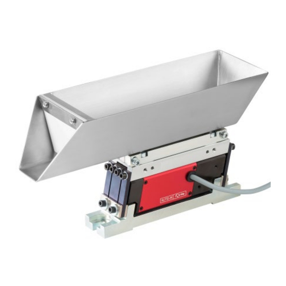
Vibrating refill hopper
NVB07/0.5
Translation of the Original Assembly Instructions EN
Vibrating refill hopper NVB07/0.5 (230 V / 50 Hz)
Vibrating refill hopper NVB07/0.5 (115 V / 60 Hz)
Vibrating refill hopper NVB12/1.0 (230 V / 50 Hz)
Vibrating refill hopper NVB12/1.0 (115 V / 60 Hz)
Vibratory refill hopper NVB25/3.0 (230 V / 50 Hz)
Vibratory refill hopper NVB25/3.0 (115 V / 60 Hz)
Operating & Installation Instructions
I
NVB12/1.0
Order no: 50398072
Order no: 50439559
Order no: 50398076
Order no: 50439561
Order no: 50398089
Order no: 50439562
EN
NVB07/0.5/NVB12/1.0/NVB25/3.0
I
NVB25/3.0
Date 02.12.2023
Version 3.0 1–40
Advertisement
Table of Contents

Related Manuals for Afag NVB07/0.5


Summary of Contents for Afag NVB07/0.5
- Page 1 Operating & Installation Instructions Vibrating refill hopper NVB07/0.5 NVB12/1.0 NVB25/3.0 Translation of the Original Assembly Instructions EN Vibrating refill hopper NVB07/0.5 (230 V / 50 Hz) Order no: 50398072 Vibrating refill hopper NVB07/0.5 (115 V / 60 Hz) Order no: 50439559 ...
- Page 2 Your Afag team © Subject to modifications The modules have been designed by Afag Automation AG according to the state of the art. Due to the constant technical development and improvement of our products, we reserve the right to make technical changes at any time.
-
Page 3: Table Of Contents
2.8.2 Danger due to electricity ..............13 2.8.3 Mechanical hazards ................13 2.8.4 Noise hazards ..................13 Technical data ...................... 14 Dimensional drawing NVB07/0.5 - NVB25/3.0 ........... 14 Technical data NVB07/0.5 - NVB25/3.0 ............. 15 Accessories ....................16 3.3.1 Mounting parts ..................16 3.3.2 Adjustment aids .................. - Page 4 Spare and wear parts ................. 37 Decommissioning and disposal ................. 38 10.1 Safety instructions ..................38 10.2 Decommissioning ..................38 10.3 Disposal ...................... 38 4 – 40 Operating & Installation Instructions EN NVB07/0.5/NVB12/1.0/NVB25/3.0 Date 02.12.2023 Version 3.0 ...
-
Page 5: General
NOTICE This safety note points out a potentially dangerous situation which, if not avoided, can cause substantial damage to property and the environment. Operating & Installation Instructions NVB07/0.5/NVB12/1.0/NVB25/3.0 Date 02.12.2023 Version 3.0 5–40 ... -
Page 6: Additional Symbols
In these assembly instructions the following symbols are used to highlight instructions, results, references, etc. Symbol Description Instructions (steps ...) Results of actions References to sections Enumerations not ordered 6 – 40 Operating & Installation Instructions EN NVB07/0.5/NVB12/1.0/NVB25/3.0 Date 02.12.2023 Version 3.0 ... -
Page 7: Warranty
This does also apply to defective accessories and wear parts. Normal wear and tear are excluded from the warranty. The warranty covers the replacement or repair of defective Afag parts. Further claims are excluded. The warranty shall expire in the following cases: ... -
Page 8: Safety Instructions
observance of all instructions given in this manual. compliance with the inspection and maintenance work and the specifications in the data sheets, using only original spare parts. 8 – 40 Operating & Installation Instructions EN NVB07/0.5/NVB12/1.0/NVB25/3.0 Date 02.12.2023 Version 3.0 ... -
Page 9: Foreseeable Misuse
observe and communicate universally applicable laws and regulations regarding accident prevention and environmental protection, provide the necessary personal protective equipment (e.g., protective gloves) and instruct the personnel to wear it. Operating & Installation Instructions NVB07/0.5/NVB12/1.0/NVB25/3.0 Date 02.12.2023 Version 3.0 9–40 ... -
Page 10: Obligations Of The Personnel
Authorized persons who due to their specialized professional training, expertise and experience can identify risks and preventing hazards arising from the use of the machine. 10 – 40 Operating & Installation Instructions EN NVB07/0.5/NVB12/1.0/NVB25/3.0 Date 02.12.2023 Version 3.0 ... -
Page 11: Personal Protective Equipment (Ppe)
6.2 "Assembly" and chap. 7.3 "Settings". Afag Automation AG accepts no liability for unauthorised changes or improper assembly, installation, commissioning, maintenance, or repair work. The modules may not be changed or modified in any way, except with the prior written consent of Afag. - Page 12 Only qualified personnel may work with or on the module. Read this manual carefully before carrying out any work on or with the module. 12 – 40 Operating & Installation Instructions EN NVB07/0.5/NVB12/1.0/NVB25/3.0 Date 02.12.2023 Version 3.0 ...
-
Page 13: Danger Due To Electricity
In certain cases, an impermissible noise level may result (e.g. when opening the lid of the noise protection hood for filling or refilling the parts). Wear hearing protection during noise-critical activities! Operating & Installation Instructions NVB07/0.5/NVB12/1.0/NVB25/3.0 Date 02.12.2023 Version 3.0 13–40 ... -
Page 14: Technical Data
Technical data Technical data Dimensional drawing NVB07/0.5 - NVB25/3.0 Fig. 1 Dimensional drawing - NVB07/0.5 – NVB25/3.0 14 – 40 Operating & Installation Instructions EN NVB07/0.5/NVB12/1.0/NVB25/3.0 Date 02.12.2023 Version 3.0 ... -
Page 15: 3.2 Technical Data Nvb07/0.5 - Nvb25/3.0
Technical data 3.2 Technical data NVB07/0.5 - NVB25/3.0 Operating & Installation Instructions NVB07/0.5/NVB12/1.0/NVB25/3.0 Date 02.12.2023 Version 3.0 15–40 ... -
Page 16: Accessories
115V/60Hz 50360106 The Afag linear feeders are available in 230V/50Hz and 115V/60Hz versions. Various Afag control units are available to control the linear feeders. For more information on the controller, see chap. 6.3.1 and the controller manufacturer's ... -
Page 17: Transport, Packaging And Storage
The module must not be lifted at the conveyor rail! Using the conveyor rail as a lifting point can damage the module! Lift the module by the base only! The Afag modules are packed in the original packaging (cardboard box). Carefully remove the module from the original packaging. Scope of supply The corresponding documentation is supplied with each module (e.g. -
Page 18: Transport
The weight of the mode depends on the respective version and can be taken from the transport documents. Packaging The module is transported packed on a pallet. If Afag packaging is not used, the module must be packed in shock and dust-proof packaging. NOTICE... -
Page 19: Design And Description
Electromagnetic vibrations are converted in the NVB to store and convey piece goods. The parts are moved in the conveying direction by micro-jumps. The vibrating refill hoppers NVB consist of a vibrating trough and an Afag linear feeder from the HLF-M series. -
Page 20: Installation, Assembly And Setting
Observe the safety instructions in chap. 2 "Safety instructions" of this manual as well as the instructions in chap. 6.3. 20 – 40 Operating & Installation Instructions EN NVB07/0.5/NVB12/1.0/NVB25/3.0 Date 02.12.2023 Version 3.0 ... -
Page 21: Assembly
79.0 117.0 135.0 125.0 185.0 215.0 195.0 280.0 330.0 280.0 390.0 460.0 390.0 560.0 650.0 530.0 750.0 880.0 670.0 960.0 1120.0 1000.0 1400.0 1650.0 1350.0 1900.0 2250.0 Operating & Installation Instructions NVB07/0.5/NVB12/1.0/NVB25/3.0 Date 02.12.2023 Version 3.0 21–40 ... -
Page 22: Mounting Instruction
( chap. 7.3.1). The height adjustment must be made by means of appropriate substructures. Suitable Afag standard components are available for complete station set-ups. 22 – 40 Operating & Installation Instructions EN NVB07/0.5/NVB12/1.0/NVB25/3.0 Date 02.12.2023... -
Page 23: Electrical Connection
All IRG types operate with soft-starting and offer different options for mounting, attachment and control. A detailed description of the controller can be found in the AFAG general catalogue. Third-party control units can also be used, provided they meet the technical conditions. -
Page 24: Operation
The use of the operating software is described in the installation instructions for the controllers used. 2. If the module is supplied with an Afag controller, no further action is required (operating parameters already stored in the controller). 3. When using a different controller, special cables must be made, and the operating parameters determined. -
Page 25: First Commissioning
7.3.1 Adjust mass compensation The vibrating forces in the base plate of the Afag NVB are compensated al- most completely due to the principle of opposing vibrations. To ensure this vibration force compensation, the following conditions must be observed in the design of the conveyor rail: 1. -
Page 26: Setting The Natural Frequency
2.5 ± 0.1 7.3.2 Setting the natural frequency The Afag vibratory refill hopper is a spring-mass vibrating system and works by exploiting resonance behaviour. Weights that are not exactly balanced require a spring stiffness modification. For this purpose, sliding adjustment plates (1) are mounted on the base plate attachment of the spring assemblies. - Page 27 Push the adjustment plates upwards or, if necessary, install an additional leaf spring. Carry out the test for fine adjustment of the natural frequency (see above) again. The process is completed. Operating & Installation Instructions NVB07/0.5/NVB12/1.0/NVB25/3.0 Date 02.12.2023 Version 3.0 27–40 ...
-
Page 28: Adjust Air Gap
4. Tighten the fastening screws (2) alternately in stages to achieve parallelism of the surfaces. The process is completed. 28 – 40 Operating & Installation Instructions EN NVB07/0.5/NVB12/1.0/NVB25/3.0 Date 02.12.2023 Version 3.0 ... -
Page 29: Fault Elimination
Ensure that the protective earthing of the power supply is in perfect condition. Observe the safety instructions in chap. 2 "Safety instructions" of these installation instructions as well as the safety instructions of the controller manufacturer. Operating & Installation Instructions NVB07/0.5/NVB12/1.0/NVB25/3.0 Date 02.12.2023 Version 3.0 29–40 ... -
Page 30: Fault Causes And Remedy
Setting the conveyor: Operating Instructions Foreign part is stuck in the air gap Remove foreign part between magnet and armature 30 – 40 Operating & Installation Instructions EN NVB07/0.5/NVB12/1.0/NVB25/3.0 Date 02.12.2023 Version 3.0 ... - Page 31 Variation of the position of too far away from excitation the adjustment plates. Tighten the screws frequency of the spring assemblies. Setting the conveyor: Operating Instructions Operating & Installation Instructions NVB07/0.5/NVB12/1.0/NVB25/3.0 Date 02.12.2023 Version 3.0 31–40 ...
- Page 32 Setting the conveyor: Operating Instructions Foreign part jammed in the air gap Remove foreign part between payload and counterweight 32 – 40 Operating & Installation Instructions EN NVB07/0.5/NVB12/1.0/NVB25/3.0 Date 02.12.2023 Version 3.0 ...
-
Page 33: Maintenance And Repair
Observe the operating instructions of the controller used! Also observe the safety instructions in chap. 2 „Safety instructions“ in this manual. Operating & Installation Instructions NVB07/0.5/NVB12/1.0/NVB25/3.0 Date 02.12.2023 Version 3.0 33–40 ... -
Page 34: Maintenance Activities And Maintenance Intervals
Observe notes chap 9.3.2! Leaf spring Check, remove if As required [Off] necessary, clean / replace chap. 9.3.3! Removal, cleaning, replacement 34 – 40 Operating & Installation Instructions EN NVB07/0.5/NVB12/1.0/NVB25/3.0 Date 02.12.2023 Version 3.0 ... -
Page 35: Notes On Cleaning
Vacuum clean before rubbing Hoover and anti-static PET / Makrolon / Plexi down, then spray with an anti- spray static spray and rub off Operating & Installation Instructions NVB07/0.5/NVB12/1.0/NVB25/3.0 Date 02.12.2023 Version 3.0 35–40 ... -
Page 36: Remove Leaf Springs
Clean working area No use of splash water. No abrasion or process dusts. Environmental conditions as specified in the technical data. 36 – 40 Operating & Installation Instructions EN NVB07/0.5/NVB12/1.0/NVB25/3.0 Date 02.12.2023 Version 3.0 ... -
Page 37: Spare And Wear Parts
50203471 NVB25/3.0 Leaf spring 50254134 Please note that Afag does not assume any warranty for modules that have not been replaced or repaired by Afag! Spare parts for the vibratory refill hopper are available on request. Operating & Installation Instructions NVB07/0.5/NVB12/1.0/NVB25/3.0... -
Page 38: 10 Decommissioning And Disposal
Electronic parts, electrical scrap, auxiliary and operating materials must be disposed of by approved specialist companies. Information on proper disposal can be obtained from the responsible local authorities. 38 – 40 Operating & Installation Instructions EN NVB07/0.5/NVB12/1.0/NVB25/3.0 Date 02.12.2023 Version 3.0 ... - Page 39 Operating & Installation Instructions NVB07/0.5/NVB12/1.0/NVB25/3.0 Date 02.12.2023 Version 3.0 39–40 ...
- Page 40 40 – 40 Operating & Installation Instructions EN NVB07/0.5/NVB12/1.0/NVB25/3.0 Date 02.12.2023 Version 3.0 ...
Need help?
Do you have a question about the NVB07/0.5 and is the answer not in the manual?
Questions and answers