Advertisement
MCX2 and MCX8 Installation Manual
This document contains minimum information that is necessary for initial setup
and installation of the device. The detailed description of configuration
parameters and functionalities is specified in respective Operating Manual
available at www.roger.pl.
I
NTRODUCTION
The expander is designed to operate in RACS 5 system as peripheral device
connected to RS485 bus of MC16 access controller. Factory new device is
configured with default settings including ID=100 address. Before connecting to
MC16 controller, the device should be assigned with unoccupied address in
range of 100-115. Programming of other parameters depends on the individual
requirements and is not obligatory. Configuration of the expander with
RogerVDM requires RUD-1 interface.
C
R
ONFIGURATION WITH
OGER
Fig. 1 Connection of the expander to RUD-1 interface for configuration
Programming procedure with RogerVDM software:
1. Connect the device to RUD-1 interface (fig. 1) and connect the RUD-1 to
computer's USB port.
2. Restart the device (press RESET button or switch power supply off and on).
3. Within 2-3 seconds place jumper on JP7 contacts (fig. 3 or fig. 4) and LED
PWR will pulsate quickly.
4. Start RogerVDM program, select MCX v2.x device, v2.0 firmware version,
RS485 communication channel and serial port with RUD-1 interface.
5. Click Connect, the program will establish connection and will automatically
display Configuration tab.
6. Enter unoccupied RS485 address in range of 100-115 and other settings
according to requirements of specific installation.
7. Click Send to Device to update the configuration of device.
8. Optionally make a backup by clicking Send to File... and saving settings to
file on disk.
9. Remove jumper from JP7 contacts and disconnect device from RUD-1
interface.
F
IRMWARE UPDATE
The update requires connection of expander to computer with RUD-1 interface
(fig. 2) and starting RogerVDM software. The latest firmware file is available at
www.roger.pl.
Firmware update procedure:
1. Connect the device to RUD-1 interface (fig. 1) and connect the RUD-1 to
computer's USB port.
2. Place jumper on FDM contacts (fig. 3 or fig. 4).
3. Restart the device (press RESET button or switch power supply off and on).
4. Start RogerVDM program and in the top menu select Tools and then Update
firmware.
5. In the opened window select device type, serial port with RUD-1 interface
and path to firmware file (*.hex).
6. Click Update to start firmware upload with progress bar in the bottom.
7. When the update is finished, remove FDM jumper and restart the device.
Roger Access Control System
MCX2 / MCX8 Installation Manual
Firmware version: 2.0.24 and newer
Document version: Rev. D
VDM P
ROGRAM
Hardware version: 2.0
Fig. 2 Connection of the expander to RUD-1 interface for firmware update
A
PPENDIX
Fig. 3 MCX2 expander
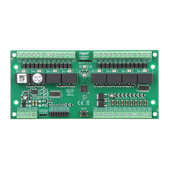
Fig. 4 MCX8 expander
Table 1. Screw terminals
Screw terminal
+12V
GND
A
B
COM
NC
NO
IN1..IN8
Description
12VDC power supply
Ground
RS485 bus, line A
RS485 bus, line B
RELx relay common terminal
RELx relay output (NC)
RELx relay output (NO)
IN1..IN8 input line
2019-10-11
1/2
Advertisement
Table of Contents

Subscribe to Our Youtube Channel
Related Manuals for Roger MCX2


Summary of Contents for Roger MCX2
- Page 1 MCX2 and MCX8 Installation Manual 2019-10-11 Roger Access Control System MCX2 / MCX8 Installation Manual Firmware version: 2.0.24 and newer Hardware version: 2.0 Document version: Rev. D This document contains minimum information that is necessary for initial setup and installation of the device. The detailed description of configuration parameters and functionalities is specified in respective Operating Manual available at www.roger.pl.
- Page 2 Weight of the equipment is specified in the document. Contact: Roger Sp. z o. o. sp. k. 82-400 Sztum Gościszewo 59 Tel.: +48 55 272 0132 Fax: +48 55 272 0133 Tech.
Need help?
Do you have a question about the MCX2 and is the answer not in the manual?
Questions and answers