
Related Manuals for Roger MCX4D


Summary of Contents for Roger MCX4D
- Page 1 Roger Access Control System MCX4D Operating Manual Product version: 1.0 Firmware version: 1.1.18 or newer Document version: Rev. H...
-
Page 2: Design And Application
MCX4D which is supplied from PSU equipped with own backup (e.g. UPS) can be supplied with 12-15VDC but then it cannot be equipped with own backup battery. -
Page 3: Backup Battery
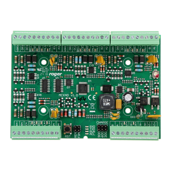
12.11.2020 Backup battery MCX4D enables battery charging with 0.3A, 0.6A or 0.9A current up to the level of voltage supplied to the expander (nominal 13.8VDC). The current is selected with jumpers (fig. 2). When battery voltage drops to approximately 10V then it is disconnected from expander. The battery is reconnected when the 13.8V supply to expander is restored. - Page 4 MCX4D Operating Manual 12.11.2020 configuration (RogerVDM). Input functions are assigned within high level configuration (VISO). Multiple functions can be assigned to the same input at the same time. In standard scenario of door control, DC inputs are dedicated to connection of door contacts while DR inputs...
-
Page 5: Transistor Outputs
MCX4D Operating Manual 12.11.2020 Parametric resistors The same values of parametric resistors are used for all inputs i.e. 1kΩ; 1,2kΩ; 1,5kΩ; 1,8kΩ; 2,2kΩ; 2,7kΩ; 3,3kΩ; 3,9kΩ; 4,7kΩ; 5,6kΩ; 6,8kΩ; 8,2kΩ; 10kΩ; 12kΩ. In case of 3EOL/DW (Double Wiring) input type, Alarm A resistor defines a value of resistor used to detect triggering of the first input while Alarm B resistor defines a value of resistor used to detect triggering of the second input. - Page 6 MCX4D Operating Manual 12.11.2020 Fig. 2 MCX4D expander Table 3. MCX4D screw terminals Name Description BAT+, BAT- Backup battery VIN+, VIN- 13.8VDC input power supply AUX+, AUX- 13.8VDC/0.2A output power supply (for general purpose) VOUT+, VOUT- 13.8VDC/0.2A output power supply (to controller)
-
Page 7: Operation Scenarios
MCT devices must have unique addresses. For example, in case of read-in/out doors it is possible to control max. 7 doors in such setup as MC16-PAC-7 + 2 x MCX4D + 14 x MCT while in case of read-in doors it is possible to control max. - Page 8 MCX4D Operating Manual 12.11.2020 Fig. 4 Scenario of operation with MC16-PAC-4-KITs Fig. 5 Scenario of operation with multiple MCX4D expanders 8/13...
-
Page 9: Low Level Configuration (Rogervdm)
MCX4D Operating Manual 12.11.2020 Fig. 6 Connection diagram for MCX4D expander in MC16-PAC-4-KIT 4. C ONFIGURATION Low level configuration (RogerVDM) The purpose of low level configuration is to prepare device for operation in RACS 5 system. Programming procedure with RogerVDM software: 1. - Page 10 MCX4D Operating Manual 12.11.2020 Fig. 7 Connection to RUD-1 interface (low level configuration) Table 4. List of low level parameters Communication settings RS485 address Parameter defines device address on RS485 bus. Range: 100-115. Default value: 100. RS485 communication timeout [s] Parameter defines delay after which device will signal lost communication with controller.
-
Page 11: High Level Configuration (Viso)
The purpose of high level configuration is to define logical functioning of the expander which communicates with the MC16 access controller and it depends on applied scenario of operation. The example of access control system configuration is given in AN006 application note which is available at www.roger.pl. 5. F IRMWARE UPDATE The update requires connection of expander to computer with RUD-1 interface (fig. -
Page 12: Specification
13.8VDC; +/- 100mV (backup battery connected) 11-15 VDC (no backup battery) Current consumption MCX4D expander: 50mA (average) MCX4D expander with maximal load at power outputs and maximal battery charging current: 6.0A Battery charging current Configurable: 0.3A/0.6A/0.9A Inputs Eight (DCx, DRx) parametric inputs... -
Page 13: Ordering Information
4-door expander; battery charge and maintenance; 13.8 VDC supply MC16-PAC-3-KIT 3-door access control kit; ME-16 metal enclosure; MC16-PAC-3 access controller module; MCX4D I/O expander; PS4D power supply MC16-PAC-4-KIT 4-door access control kit; ME-16 metal enclosure; MC16-PAC-4 access controller module; MCX4D I/O expander; PS4D power supply...
Need help?
Do you have a question about the MCX4D and is the answer not in the manual?
Questions and answers