Table of Contents
Advertisement
Advertisement
Table of Contents

Subscribe to Our Youtube Channel
Related Manuals for biodex BioSway


Summary of Contents for biodex BioSway
- Page 1 BIOSWAY PORTABLE BALANCE SYSTEM OPERATION MANUAL 950-460 950-461 IODEX Biodex Medical Systems, Inc. 20 Ramsey Road, Shirley, New Y ork, 11967-4704, Tel: 800-224-6339 (Int’l 631-924-9000), Fax: 631-924-9338, Email: info@biodex.com, www.biodex.com FN: 10-202 Rev B 4/11...
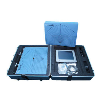
- Page 2 BIOSWAY PORTABLE BALANCE SYSTEM This manual covers installation and operation procedures for the following products: 950-460 BioSway Portable Balance System w/o Case 950-461 BioSway Portable Balance System w/Case CAUTION: Federal law restricts this device to sale of or on the order of a medical practitioner.
- Page 3 10. compatIble prInterS and component part lISt ..........10-1 appendIx a: balance SyStem ClInIcal teSt of SenSory InteGratIon and balance (ctSIb) Sway Index equatIon........a-1 • Test Description ..........................A-1 • Equipment Description......................A-1 appendIx b: bIoSway relIabIlIty and ctSIb normatIve data......b-1 — III — TABLE OF CONTENTS...
- Page 4 INTRODUCTION appendIx c: movement StrateGIeS for balance, SenSory orGanIzatIon, aGe-related chanGeS In balance and ctSIb teSt reSult InterpretatIon ....c-1 • Movement Strategies ........................C-1 • Sensory Organization For Balance ..................C-2 • Age-Related Changes In Balance....................C-4 • CTSIB Test Result Interpretation ....................C-5 appendIx d: addItIonal noteS about ctSIb report InterpretatIon •...
-
Page 5: Introductiontable Of Contents
Clinical Test of Sensory Integration and Balance protocol. The easy-to-follow touch screen format makes BioSway simple to learn and operate. All test results and training sessions can be stored and printed. Comparison to normative data helps to communicate need, progress and outcome. - Page 7 2. SYSTEM SPECIFICATIONS Includes: Balance Platform, Color Touch Screen LCD display, Indexed Foam Pad, Blindfold, Power supply and cables, Data collection software, Serial Cable and USB adapter Power: 115V/ 230VAC, 50/60 HZ, 15 amp line This system uses APS (Advanced Power Solutions) Power Supply Part #: APS22ES-150160/KOB Order #:1101-00396 Line Voltage:...
- Page 8 0 to 40°C Humidity: 0 to 90% rh, non-condensing For optimum performance, the BioSway should be operated in a normal environment where the temperature and humidity are maintained for normal human comfort. Certification: ETL and cETL listed to UL 60601-1, CAN/CSA C22.2 No.:601-1-M90 and EN60601-1...
-
Page 9: Connections And Adjustments
3. CONNECTIONS AND ADJUSTMENTS The BioSway is quick and easy to assemble. Simply remove the shipping knob and store it in the handle, connect the components as described on the connection instruction placard, and level the platform as needed. The entire process should take only a few minutes. -
Page 10: System Specifications
SYSTEM SPECIFICATIONS base to display connections (See Figure 3.4.) Connect the cable with the 15 pin Female D connector to the display. Connect the 15-pin Male D connector at the opposite end of the cable to the base. Figure 3.4. Base to display connections. ac power connections (See Figure 3.5.) Plug the power supply into wall current. -
Page 11: Assembly And Installation
Serial connection to laptop or pc (See Figure 3.7.) The serial connection is used to connect the BioSway to a laptop or PC. NOTE: See Chapter 9, System Utilities, for more information on patient data collection software. Figure 3.7. Serial connection to a laptop or PC. - Page 12 platform Setup (See Figures 3.8 and 3.9.) This routine ensures the platform is level. The platform is level when all four markers on the display are green. Adjustment Knob Figure 3.8. Figure 3.9. Figures 3.8 and 3.9. Use the Adjustment Knob to compensate for floor irregularities when leveling the platform.
- Page 13 950-465 BioSway Display Stand, Telescoping table top Stand for bioSway display (included) The Table Top Stand fits into the BioSway case for portability and can also be wall mounted. bioSway display on telescoping Stand (sold separately) The Telescoping Stand adjusts vertically: 39”to 69” (99 to 175 cm) – measuring from the top of the display.
- Page 14 CONTENTS connecting the display to the telescoping Stand: Figure 1. Figure 2. Figure 3. - Release Tab shown. connecting and disconecting to/from the telescoping Stand • Position so it clicks in place (See Figure 1 and 2) • Press the release tab to remove. (See Figure 3) connecting the display to the table top Stand: use the table top Stand for a wall mounted display CONNECTIONS AND ADJUSTMENTS...
- Page 15 CONTENTS mount the display to veSa mIS-d The BioSway Display mount even allows for direct attachment to other 100 mm VESA MIS-D compatible display mounts. It is best to leave the black mounting plate in place. VESA MIS-D is a common interface for a wide variety of monitor products.
-
Page 16: Clinical Considerations
An outstretched arm, not touching is reassuring for the patient. Figure 4.1. Figure 4.2. Figures 4.1 and 4.2. Ensure all users have a verbal understanding of the BioSway before using the device. Never allow a patient to use the BioSway without supervision. balance overvIew Maintaining postural balance involves complex coordination and integration of multiple sensory, motor, and biomechanical components as graphically represented below. - Page 17 CONTENTS components of balance (See Figure 4.3.) Postural balance involves special sensory receptors that provide information in regards to vari- ous environmental and physiological conditions that may affect a person’s ability to maintain equilibrium. They are as follows: Figure 4.3. Components of balance. vestibular apparatus The vestibular apparatus (VA) consists of three semicircular canals, and provides sensory infor- mation in regards to head position and gravitational changes.
- Page 18 CLINICAL CONSIDERATIONS proprioception and Kinesthetic Input The proprioceptive component of balance involves mechanoreceptors located within the skin, muscle tendons, and ligaments surrounding a joint. These structures play an important role in providing sensory information relating to touch, body position and rate of movement from external cues or conscious movement patterns associated with daily living.
- Page 19 Another version of this test called the modified CTSIB is often used. The m-CTSIB eliminates conditions 3 and 6. The BioSway uses the M-CTSIB format of 4 conditions as the default with the ability to include the other 2 if desired.
- Page 20 • Sway Index Stability Index and Sway Index The BioSway tracks the subjects sway angle and direction from center. This measure is called the Stability Index. The Stability index is the average position from center. Specific information on how the Stability index is calculated can be found in the appendix. The Stability index does not indicate how much the patient swayed only their position.
- Page 21 CLINICAL CONSIDERATIONS references Nashner, L., Practical biomechanics and physiology of balance. Handbook of Balance Function and Testing, 1993 Irrgang JJ, Whitney SL, Cox, ED: Balance and proprioceptive training for rehabilitation of the lower extremity. J Sport Rehabilitation 3:68-83, 1994 Vander, A., J. Sherman, and D. Luciano. Human Physiology: The Mechanisms of Body Function [5 th ed.], 1990 Clark S, Rose DJ, Fujimoto K.
-
Page 22: Getting Started
5. GETTING STARTED PRELIMINARIES The BioSway software program is easy to master. Simply follow the screen prompts as they lead you step-by-step through testing and training protocols or software utility options. the maIn menu (See Figure 5.1.) To access the BioSway System Main Menu: 1. - Page 23 6. THE TRAINING MODESAPPLICATIONS Figure 6.1. The Training screen. The training modes provide a simple means of setting up Balance training sessions. Six interac- tive game-like training modes are provided. These allow for fast patient setups and less formal protocols than the testing. All training modes can be customized to provide specific rehab goals with the on-screen grid and score-keeping functions used to both help motivate users and keep them focused on the task at hand.
- Page 24 NOTE: Patient Height is entered so that the patient’s Center of gravity can be estimated. 55% of the patient’s height is used to calculate where the COG is. Based on the COG height, the BioSway takes into account that the theoretical angular excursion of the COG is different for different height people.
-
Page 25: Computer Preliminaries
COMPUTER PRELIMINARIES 7. To clear any misplaced or unwanted targets, touch <Clear Target>. Each time this key is pressed, the most recent target added to the screen will be removed. 8. Touch <More Options> to advance to the Postural Stability Training Options screen if desired. - Page 26 COMPUTER PRELIMINARIES lImItS of StabIlIty (loS) traInInG routIne (See Figure 6.3.) Figure 6.3. The Limits of Stability (LOS) Training screen. The Limits of Stability Training screen is designed to challenge the user to move through a movement pattern consistent with the sway envelope. The sway envelope is that area a person can move their COG within their base of support.
-
Page 27: Operation
2. OPERATION 4. Explain the training protocol to the patient, then press <Start> to begin the LOS training ses- sion. The LOS Training screen reflects the patient’s stability performance through the course of the LOS training session. The Elapsed Time from the start of the training session is shown at the top right of the display while the stability level is illustrated by a bar graph. - Page 28 weIGht ShIft traInInG (See Figure 6.5.) Figure 6.5 The Weight Shift Training screen. This training mode allows for exercise in the most basic of activities; weight shifting. The patient has the ability to shift weight in medial/lateral, anterior/posterior and diagonal planes. During this training routine the target zone, defined by two parallel lines, can be rotated to any of three positions while the amount of excursion within the target area can be modified to allow for the most limited to most difficult degree of weight shifting.
- Page 29 TESTING A PATIENT 3. Touch <More Options> to advance to the Weight Shift Training Options screen if desired. Here you can set the total hits for the exercise (default = 60), turn tracing ON/OFF and set Scoring Tone ON/OFF. Touch <OK> to confirm your selections and return to the Weight Shift Training Options screen, or <Cancel>...
- Page 30 maze control traInInG (See Figures 6.6 and 6.7.) This mode allows the patient to follow a reproducible pattern of movement throughout a maze in both static and dynamic environments. Three skill levels allow the maze to be modified to create a simple or more difficult environment for the patient to navigate through. Time counts up or down as set.
- Page 31 3. Touch <More Options> to advance to the Maze Control Training Options screen if desired. Here you can set the total time for the exercise, and turn tracing ON/OFF. Touch <OK> to confirm your selections and return to the Maze Control Training Options screen, or <Cancel> to return to the Maze Control Training Options screen without making changes.
- Page 32 CONTENTS random control traInInG (See Figures 6.8 and 6.9.) The Random Control training mode allows the patient to perform neuromuscular control activi- ties in random patterns generated by the display and is ideal for motor control and vestibular training. The size and speed of the target can be modified for progressions ranging from easy to difficult.
- Page 33 CONTENTS Figure 6.9. The Random Control Training screen. percent weIGht-bearInG traInInG (See Figures 6.10 and 6.11.) Percent Weight-Bearing Training provides real-time feedback of the percentage of weight-bear- ing on the patient’s foot, ankle, knee, hip, body side, etc. In this mode targets can be set that encourage patients to focus on Percent weight-bearing goals in anterior, posterior, medial and lateral movements.
- Page 34 CONTENTS Figure 6.11. The Percent Weight Bearing Training screen. Scoring is the percent of time spent within the target range. Figure 6.12. The position patient screen is used to adjust and record the patient’s foot position prior to beginning the training exercise. THE TRAINING MODES —...
- Page 35 CONTENTS percent weight bearing training access and differences from other modes Access to Percent Weight-Bearing Training Mode is similar to other modes with the following differences: 1. This is the one training mode where positioning the patient is required. Position the patient’s feet as noted.
- Page 36 7. TESTING Static testing measures the angular excursion of the patient’s center of gravity. Body height must come into play for static measures. A person’s Center of Gravity (COG) is approximately 55% of their height. Based on the selected height an appropriate static measure scaling is applied. Testing provides a baseline for rehabilitation programs as well as balance screening.
-
Page 37: Service Procedures
SERVICE PROCEDURES the poStural StablItIy teSt (See Figure 7.2.) The Postural Stability Test emphasizes a patient’s ability to maintain center of balance. The patient’s score on this test assesses deviations from center, thus a lower score is more desirable than a higher score. Figure 7.2. - Page 38 12. Touch <More Options> to advance to the Postural Stability Test Options screen if desired. Here you can set the Test Trial Time, enter initial and ending platform stability settings, enter the number of trials, enter the Rest Countdown, or toggle bilateral comparison to “Yes” or “No”...
- Page 39 performInG a lImItS of StabIlIty teSt (See Figure 7.3.) Testing is usually done at 75% LOS, which is the moderate skill level. Easy skill level is 50% and hard skill level is 100% of the sway envelop. Scoring percentage-based and reflects the direction- al accuracy of the movement to the blinking targets (see Appendix for details on scoring).
- Page 40 performInG a ctSIb teSt (See Figures 7.4 – 7.7.) To perform the CTSIB test, simply follow screen prompts. Other points of interest: 1. Touch <More Options> to advance to the CTSIB Test Options screen if desired. Here you can set the Test Trial Time, enter the number of trials and enter the Rest Countdown, and change which conditions you want to test by simply touching to highlight the conditions you want to do.
- Page 41 Figure 7.5. The m-CTSIB Testing screen with cursor turned OFF. Figure 7.6. The m-CTSIB Testing screen prepared for condition #2. 2. Again as with the other tests you will have the option to perform a trial rep prior to each test condition rep.
- Page 42 Figure 7.7. The m-CTSIB Test Results screen. 4. At the Results screen, touch <Print> to automatically generate a printed report if desired. 5. To save the test data, touch <Save Results> and then touch <OK> in response to the “Save Results for later reporting or export?”...
-
Page 43: Report Parameters
8. REPORTS AND DATA The BioSway offers reports for each of the test modes. These can be used to objectively measure and record the patient’s balance ability. Progress reports that graph overall stability scores from each test date are also available. - Page 44 Xn = n th sample X = mean deflection data InterpretatIon for the lImItS of StabIlIty Since the BioSway measures COG angular displacement from center it can be used to assess a patient’s LOS in two ways. method 1 Using the Stability Index (SI) gained from a Dynamic Balance Report it can be determined how well a patient controls their balance within their LOS in both an Anterior/Posterior (A/P) direc- tion and a Medial/Lateral direction (M/L).
-
Page 45: General Maintenance
GENERAL MAINTENANCE dynamIc lImItS of StabIlIty Score calculatIon dloS Score % = Straight Line Distance to Target x Actual Distance Traveled where: Actual Straight Line Distance Distance to Target Traveled (trace) CENTER TARGET overall dloS Score: I =8 ∑ (DLOS Scores) I =1____________________ Or the Average of all 8 Targets —... - Page 46 SERVICE PROCEDURES Sample balance reportS (See Figures 8.1 – 8.4.) Figure 8.1. The Postural Stability Test Report. REPORTS AND DATA — 8-4 —...
-
Page 47: Replacement Parts
REPLACEMENT PARTS Figure 8.2. A Limits of Stability Test Report. — 8-5 — REPORTS AND DATA... - Page 48 Figure 8.3. CTSIB Sample report, 6 conditions. Note that if the patient failed to complete a condition, it would be denoted as “FELL.” REPORTS AND DATA — 8-6 —...
- Page 49 SCHEMATICS proGreSS reportS (See Figure 8.4.) Progress Reports graph overall stability scores for each Postural Stability Test date selected. The tests are selected from Patient Maintenance on the Utilities Menu. The patient selected must have multiple tests, with resultant Stability Index scores, to generate a report. To Print A Progress Report: 1.
-
Page 50: System Utilities
9. SYSTEM UTILITIES The System Utilities allow users to access the System Configuration and Patient Management screens. To access the System Utilities, touch <Utilities> on the Main Menu. The System Utilities screen should now be displayed. From here you can select Configuration or Patient Management by touching the desired icon. - Page 51 CONTENTS confIGuratIon Touch <Configuration> and then enter 781 in response to the “Enter Access Code” prompt. Touch <OK>. The Configuration screen should now be displayed. At this screen users can set values for Screen Time Out, Date/Time and Default Settings. You can also turn Tone ON/OFF, adjust LCD brightness or Tone volume, and select Measurement Units, Printer Resolution or CTSIB Defaults.
- Page 52 CONTENTS turn tone on/off: This setting enables or disables an audible tone which is used throughout the BioSway for scoring tones, test or exercise start signals, and completion or countdown between trials. At the Configuration screen, simply touch the ON or OFF icon to select the desired setting.
- Page 53 REPLACEMENT PARTS Figure 9.4. The m-CTSIB Age Ranges screen. At the Default Settings screen, users can set which conditions of the CTSIB they want as defaults for testing as well as the ability to enter in or change Sway Index Goals. Default settings can be restored to the “factory”...
-
Page 54: Patient Management
REPLACEMENT PARTS Figure 9.5. An Entry Access Code provides a level of security to all default settings. Secure code: Enabling this would require the 781 code to be entered each time the device is turned on. This provides some level of security. patIent manaGement (See Figure 9.5.) At the System Utilities screen, touch <Patient Management >... - Page 55 REPLACEMENT PARTS Figure 9.6. The Patient Management screen. view test results To view the results of any test displayed simply touch the desired entry on the Patient Management screen to produce an on-screen report. repeat (recalls a patient for a test or exercise session) To repeat any saved test or exercise session, touch <Repeat>...
- Page 56 Single patient delete Although the BioSway can store hundreds of CTSIB patient tests, more patients if you do less CTSIB conditions, you may want to decrease the number of stored records from time to time. To delete any full page display of saved reports, touch <Delete>.
- Page 57 SCHEMATICS multiple patient delete In addition to deleting any single patient record, multiple patient records can be deleted. 1. At the Patient Management screen touch <Multiple Delete> to delete multiple patient records. The Multiple Patient Data Delete screen should now be displayed. 2.
- Page 58 CONTENTS Figure 9.10. Custom protocols can be organized under Training or Testing. Figure 9.11. The Training Custom Protocols list. Note that all target placements and goal settings are saved and recalled for custom protocols. — 9-9 — SYSTEM UTILITIES...
- Page 59 CONTENTS Figure 9.12. The Postural Stability Training Protocol Set-Up. NOTE: All target placements and goal settings are saved and recalled for custom protocols. SYSTEM UTILITIES — 9-10 —...
- Page 60 Mini Keyboard ACK-5010U USB Keyboard Adesso AKB-210 Keyboard Adesso WKB-4000US Keyboard Adesso ACK-540UB Keyboard Adesso AKB-110B Keyboard * Printers and other devices are subject to market availability. Please check with Biodex customer service if questions arise. — 10-1 — COMPATIBLE PRINTERS...
-
Page 61: Test Description
APPENDIX A balance SyStem clInIcal teSt of SenSory InteGratIon and balance (ctSIb) Sway Index equatIon teSt deScrIptIon The objective of this test is to quantitatively determine a score defining a patient’s ability to maintain a stable vertical posture while positioned on a stationary platform. The patient is posi- tioned on a stable platform and instructed to try to maintain a stable vertical posture under a variety of sensatory conditions, eyes open, eyes closed, and vision partially obscured. - Page 62 APPENDIX B bIoSway relIabIlIty and ctSIb normatIve data BioSway Reliability and CTSIB data were collected from 100 randomly recruited people. All test subjects were healthy, active, working people. Medical history was recorded via a confidential questionnaire. The testing and protocol followed IRB approval and was performed on site.
- Page 63 APPENDIX C movement StrateGIeS for balance, SenSory orGanIzatIon, aGe-related chanGeS In balance and ctSIb teSt reSult InterpretatIon. movement StrateGIeS for balance (Robertson) According to the Systems Approach to motor control, the nervous system uses preprogrammed strategies or synergies to simplify movement. The central nervous system (CNS) takes advan- tage of pathways that link together groups of muscles in a flexible and repeatable sequence.
- Page 64 CONTENTS hip Strategy The hip strategy describes movement about the hip in response to larger losses of balance or when the support surface does not allow the use of the ankle lever, such as on an icy surface or when the surface is shorter than the length of the foot. In the hip strategy, activation of muscles is from the trunk down, or proximal to distal.
- Page 65 CONTENTS The visual system may provide inaccurate information to the nervous system. For example, a person sitting at a stoplight in a car may think she has started to move when the car next to her starts to move. The visual system “goes along” with the movement of the neighboring car and tells the brain that both cars are moving.
- Page 66 CONTENTS A person with impaired vision from a stroke or cataracts will depend less on vision and more on touch and vestibular feedback for balance. In this case, choice of assistive device, hand railings for touch, and proper lighting are important. A person with a visual impairment may perform well in a clinical setting but have difficulty with balance in more complex visual situations that demand rapid visual interpretation of multiple visual cues.
- Page 67 CONTENTS ctSIb teSt reSult InterpretatIon (Neurocom) The CTSIB is the Clinical Test for Sensory Integration and Balance. The CTSIB is the standard test for differentiating balance problems as a result of visual, vestibular or somatosensory The CTSIB uses 4 conditions to test contribution of visual, vestibular and somatosensory inputs: 1.
- Page 68 CONTENTS references Shumway-Cook A, Woollacott MH. (2001). Motor Control: Theory and Practical Applications. Philadelphia: Lippincott, Williams & Wilkins. Robertson, Lauren. Balance and Falls – continuing education course [Internet] Available from: http://www.therapyceu.com/courses/212/index_tceu.html Neurocom International. Clinical Operations Guide. Rev 8. June 2008 foot placement reference Mcllroy WE., Maki BE.
- Page 69 APPENDIX D addItIonal noteS about ctSIb report InterpretatIon The CTSIB result presentation is easy to understand and communicate if you keep the following points in mind: 1. A description of the relationship of the test condition to the sensory system is provided when the m-CTSIB protocol format of 4 conditions is used.
- Page 70 CONTENTS Figure D.2: These results indicate the patient was very unstable in the conditions with Eyes closed. They could not complete the test and as such the condition is noted as “Fell.” Figure D.3: This is the screen from the Configuration area that allows for the Sway Index Goal to be entered.
- Page 71 CONTENTS a note about ctSIb report InterpretatIon. Normal individuals have significantly more sway when standing on a foam surface versus a firm surface with eyes open, and even more sway on foam with eyes closed. However they do not become unstable or fall. Patients who become unstable or fall when standing on foam with eyes open may have difficultly using visual information for balance control and or they may have lower extremity musculoskeletal problems, which make it difficult to stand on the foam or compensate for the unstable surface.
-
Page 72: Conformance To Standards
• The BioSway Balance system should not be used adjacent to or stacked with other equipment. If the BioSway Balance system is used while positioned adjacent to other equipment, it should be observed to verify normal operation in the configuration in which it will be used. -
Page 73: Declaration Of Conformity
The BioSway Balance is intended for use in the electromagnetic environment specified below. The customer or the user of y a a a a n n n t... - Page 74 BioSway Balance is used exceeds the applicable RF compliance levels above, the BioSway Balance should be observed n a a n c i l b a a b...
-
Page 75: Recommended Separation Distances
T T a The BioSway Balance system is intended for use in the electromagnetic environment in which radiated RF disturbance are y a a l a a n a a n... -
Page 76: Cleaning And Maintenance
If you have any questions or need further assistance, contact the Biodex Customer Service Department. CAUTION: Some steps of these procedures require the BioSway to be turned ON. When this is the case, use extreme caution working on the system. - Page 77 Certified Quality Management System IODEX Biodex Medical Systems, Inc. 20 Ramsey Road, Shirley, New Y ork, 11967-4704, Tel: 800-224-6339 (Int’l 631-924-9000), Fax: 631-924-9338, Email: info@biodex.com, www.biodex.com...
Need help?
Do you have a question about the BioSway and is the answer not in the manual?
Questions and answers